
Method for reducing mine loss dilution through differentiation charge structure control blasting

A technology with structural control and differentiation, applied in blasting and other directions, can solve the problems of dilution, waste of mine resources, and increase of beneficiation costs.

Inactive Publication Date: 2017-01-04
福建省新华都工程有限责任公司
View PDF5 Cites 4 Cited by
  • Summary
  • Abstract
  • Description
  • Claims
  • Application Information

AI Technical Summary

Problems solved by technology

However, for other types of non-magnetic ores, the magnetic separation method cannot be used for beneficiation, which will inevitably result in loss and dilution of ore, a serious waste of mine resources, and increase the cost of beneficiation.

Method used


Image

  • Method for reducing mine loss dilution through differentiation charge structure control blasting
  • Method for reducing mine loss dilution through differentiation charge structure control blasting
  • Method for reducing mine loss dilution through differentiation charge structure control blasting

Examples


Embodiment 1

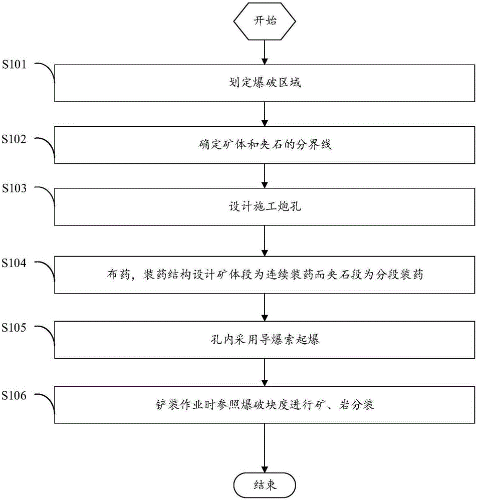
[0028] This embodiment provides a method for controlling blasting with differential charge structure to reduce loss and depletion. The technical solution includes the following steps:

[0029] Step S101: Delineate the blasting area;

[0030] Step S102: Determine the boundary line between the ore body and the interlayer;

[0031] Step S103: designing and constructing blastholes;

[0032] Step S104: distributing charges, charge structure design ore body section is continuous charge and stone interleaving section is stage charge;

[0033] Step S105: using a detonating cord to detonate in the hole;

[0034] Step S106: During the shovel loading operation, separate the ore and rock according to the size of the blasting block.

[0035] The demarcated blasting area is below the ground line 7, and the demarcated boundary between the ore body 1 and the rock 2 is clearly divided into different areas in the vertical distribution of the ore body 1 and the rock 2.

[0036] The blast hol...

Embodiment 2

[0042] This embodiment provides a method for controlling blasting with differential charge structure to reduce loss and depletion. The technical solution includes the following steps:

[0043] Step S101: Delineate the blasting area;

[0044] Step S102: Determine the boundary line between the ore body and the interlayer;

[0045] Step S103: designing and constructing blastholes;

[0046] Step S104: distributing charges, charge structure design ore body section is continuous charge and stone interleaving section is stage charge;

[0047] Step S105: using a detonating cord to detonate in the hole;

[0048] Step S106: During the shovel loading operation, the high-grade ore and the low-grade ore are subpackaged according to the blasting lumpiness.

[0049] The demarcated blasting area is below the ground line 7, the demarcated boundary between the high-grade ore body 1 and the low-grade ore body 2, and the demarcation line clearly separates the high-grade ore body 1 and the low-...


PUM


Abstract

The invention discloses a method for reducing mine loss dilution through differentiation charge structure control blasting. Different explosive unit consumptions are achieved by changing a blast hole charge structure, the lumpiness of ores obtained after blasting is obviously smaller than that of dead rock, the mutual covering and mixing degree of the ores and the rock is decreased, identifying and sorting are convenient, and mine loss dilution of the ores is reduced. The method comprises the specific steps that a blasting area is delimited; the boundary between an ore body and dunn basses is determined; construction blast holes are designed; explosives are arranged, wherein the ore body segment of the charge structure is designed to be a continuous charge segment, and the dunn bass segment of the charge structure is designed to be a segmented charge segment; detonating is conducted in the holes through detonating cords; when shovel mucking operation is conducted, ore and rock split charging is conducted by referring to the blasting lumpiness.

Description

technical field [0001] The invention relates to the technical field of mining, in particular to a method for controlling blasting with a differential charge structure to reduce loss and depletion. Background technique [0002] The loss of ore refers to the reduction in the number of ore during the mining process, resulting in a waste of resources. The dilution of ore means that waste rock is mixed into ore, or low-grade ore is mixed into high-grade ore, which reduces the grade of ore and increases the cost of beneficiation. During the mining process, waste rock is mixed, high-grade ore powder is lost, and useful components Oxidation or precipitation are depletion. [0003] Blasting in the ore-rock mixed distribution area will cause ore loss and dilution. For example, the ore is thrown into the waste rock pile by excessive blasting, and the waste rock is mixed into the ore. The blasting in the area where the ore and rock are mixed needs to be scientifically designed, and th...

Claims


Application Information

Patent Timeline
Patent Type & Authority Applications(China)
IPC IPC(8): F42D3/04F42D1/08
CPCF42D3/04F42D1/08
Inventor 崔年生
Owner 福建省新华都工程有限责任公司
Learn More