A double-acting double-rod mechanical locking cylinder with initial and final positions

A technology of mechanical locking and double rods, applied in the direction of fluid pressure actuating devices, can solve the problems of increased volume, weight and technical difficulty, disadvantages of deep-sea manned submersibles, and unsuitability for deep-sea fields, etc., achieving simple structure, The effect of light weight and high reliability

Active Publication Date: 2018-02-23
CHINA SHIP SCIENTIFIC RESEARCH CENTER (THE 702 INSTITUTE OF CHINA SHIPBUILDING INDUSTRY CORPORATION)
View PDF5 Cites 0 Cited by
  • Summary
  • Abstract
  • Description
  • Claims
  • Application Information

AI Technical Summary

Problems solved by technology

[0002] In the field of deep-sea manned submersibles, there are many mechanisms with linear reciprocating motion or limited reciprocating rotation, and the end of the stroke needs to be reliably locked. In deep-sea conditions, the hydraulic lock loses its function on land. Therefore, the traditional The scheme of oil cylinder plus hydraulic lock is not suitable for the deep-sea field. At this time, it is often necessary to design the driving mechanism and the locking mechanism separately to meet the use requirements. In addition to the complex structure of these mechanisms, in order to meet the corrosion resistance and Pressure requirements, the volume, weight and technical difficulty of the mechanism will increase significantly, which is very unfavorable for deep-sea manned submersibles that have strict requirements on volume, weight and reliability

Method used


Image

  • A double-acting double-rod mechanical locking cylinder with initial and final positions
  • A double-acting double-rod mechanical locking cylinder with initial and final positions
  • A double-acting double-rod mechanical locking cylinder with initial and final positions

Examples


Embodiment Construction

[0023] Specific embodiments of the present invention will be described below.

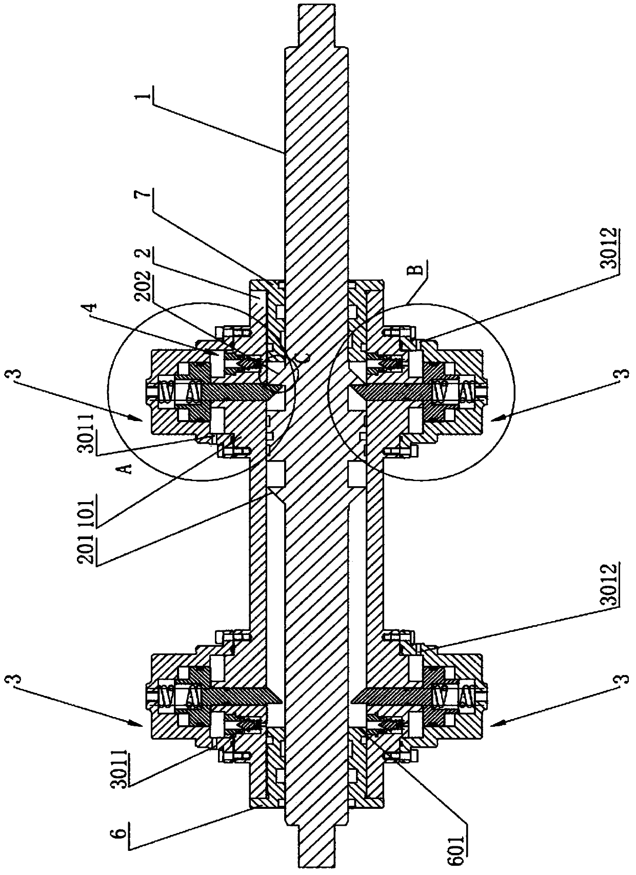
[0024] Such as figure 1 As shown, a double-acting double-rod mechanical locking oil cylinder at the beginning and end positions of the present invention includes a cylinder body 2, and the two ends of the cylinder body 2 are respectively connected to the left cylinder head 6 and the right cylinder head 7, and the piston rod 1 passes through the The left cylinder cover 6 and the right cylinder cover 7 run through and are installed in the cylinder body 2, such as figure 1 As shown, a plurality of first steps 101 are arranged symmetrically around the axis of the cylinder 2 on the outer periphery of the cylinder 2, each of the above-mentioned first steps 101 is a circular step, and the central axis of each first step 101 is aligned with the axis of the cylinder 2. axes are perpendicular to each other. Such as figure 1 As shown, block oil cylinders 3 for mechanically locking or unlocking the piston r...


PUM


Abstract

The invention discloses a double-acting double-stretching-rod initial and tail position mechanical locking oil cylinder. The double-acting double-stretching-rod initial and tail position mechanical locking oil cylinder comprises a cylinder body; the two ends of the cylinder body are separately connected with a left cylinder cover and a right cylinder cover; a piston rod is mounted in the cylinder body in a penetrating manner through the left cylinder cover and the right cylinder cover; a plurality of first steps are symmetrically arranged at the periphery of the cylinder body; a clamping block oil cylinder is arranged on each first step; a sequence valve is further arranged in each first step at one side of the cylinder body; a one-way valve is further arranged in each first step at the other side of the cylinder body; and a first wedge-shaped step and a second wedge-shaped step are separately formed by outwards extending along the periphery of the piston rod. According to the double-acting initial and tail position mechanical locking oil cylinder with double ejector rods disclosed by the invention, the piston rod can be effectively and mechanically locked when the piston rod is on a completely retracted position or a completely stretched-out position, so that the piston rod can be kept on the original position no matter positive load or negative load is applied to the tail end or the head of the piston rod. The first wedge-shaped step or the second wedge-shaped step is positioned in a gap, which does not exceed 0.2mm, between a clamping block second perpendicular surface and the inner end surface of each cylinder cover, so that locking precision is greatly improved.

Description

technical field [0001] The invention relates to the field of oil cylinders, in particular to a double-acting double-outlet rod mechanical locking oil cylinder at the beginning and end positions. Background technique [0002] In the field of deep-sea manned submersibles, there are many linear reciprocating motions or limited reciprocating rotations, and the end of the stroke needs to be reliably locked. In deep-sea conditions, the hydraulic lock loses its function on land. Therefore, the traditional The solution of oil cylinder plus hydraulic lock is not suitable for the deep sea field. At this time, it is often necessary to design the driving mechanism and the locking mechanism separately to meet the use requirements. In addition to the complex structure of these mechanisms, in order to meet the requirements of corrosion resistance and Pressure requirements, the volume, weight and technical difficulty of the mechanism will increase significantly, which is very unfavorable fo...

Claims


Application Information

Patent Timeline
Patent Type & Authority Patents(China)
IPC IPC(8): F15B15/14F15B15/26
CPCF15B15/1423F15B15/261
Inventor 刘浩胡震叶聪汤国伟张小献
Owner CHINA SHIP SCIENTIFIC RESEARCH CENTER (THE 702 INSTITUTE OF CHINA SHIPBUILDING INDUSTRY CORPORATION)
Why Eureka
Try Eureka