
Continuous circulation drilling active sealing type rotation control head and screw-on-off method thereof

A rotary control head, active sealing technology, used in sealing/isolation, earthmoving, wellbore/well components, etc., can solve the problems of unreasonable design, low rubber core opening efficiency, large volume, etc. Simple and novel effect

Active Publication Date: 2017-01-04
BC P INC CHINA NAT PETROLEUM CORP +1
View PDF7 Cites 5 Cited by
  • Summary
  • Abstract
  • Description
  • Claims
  • Application Information

AI Technical Summary

Benefits of technology

This patented technology relates to an improved design for controlling rotation during drilling that uses a special mechanism called continuously recirculated drills (CRDMs). These CRMs are designed by combining two different types of materials: one acts like valves while another works like bearings or rollers. They work together to create a tightly fitting joint between them without getting worn out easily when they come into contact again after being installed onto their respective pipes. By doing this, these devices help prevent leaks from happening around it's way through holes made at specific points along its length.

Problems solved by technology

This patented technical problem addressed in this patent relates to improving the performance and lifespan of continuously circulated tools such as drills or piping systems due to their constantly moving parts (rotor) which require lubricant during operations. Lubricants commonly found within these tools cause damage from frictional forces caused by contact with metal components like steel tubings. To address this issue, certain designs were developed where the tool's inner and outer seals could effectively protect them while still allowing easy connection/disconnection without requiring excessively large force.

Method used


Image

  • Continuous circulation drilling active sealing type rotation control head and screw-on-off method thereof
  • Continuous circulation drilling active sealing type rotation control head and screw-on-off method thereof
  • Continuous circulation drilling active sealing type rotation control head and screw-on-off method thereof

Examples


Embodiment Construction

[0028] The present invention will be further described below in conjunction with the accompanying drawings and specific embodiments, but the following embodiments in no way limit the present invention.

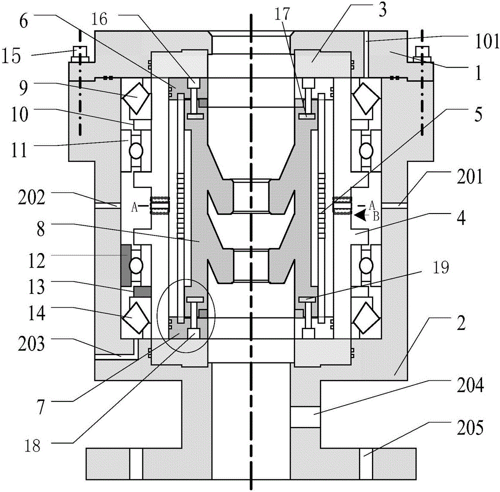
[0029] Such as figure 1 As shown, the active sealing rotary control head for continuous circulation drilling includes a rotating cylinder, a rubber core support cylinder 5, an upper rubber core pressure plate 6, a lower rubber core pressure plate 7 and a rubber core cylinder 8 arranged in a housing; wherein, The rotating cylinder, the rubber support cylinder 5 and the rubber core cylinder 8 are sequentially fitted from the outside to the inside; specifically:

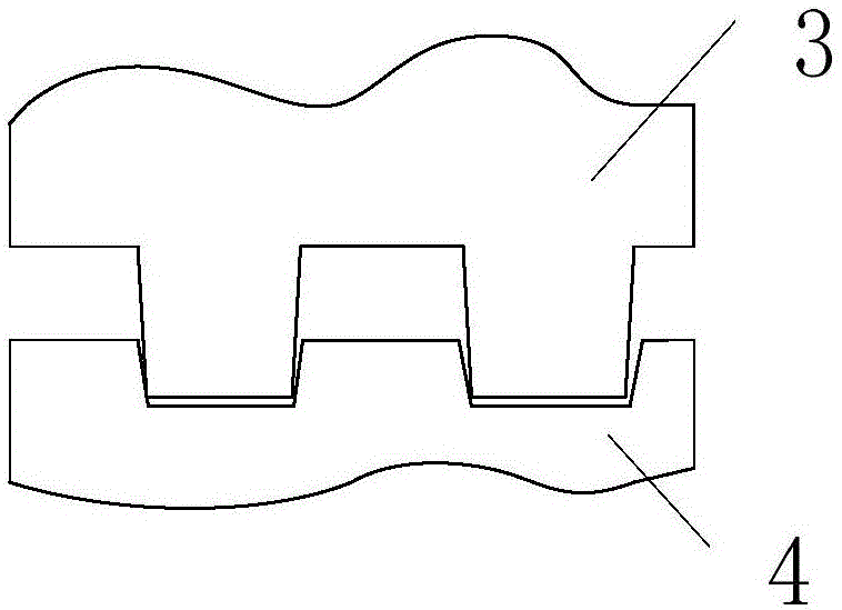
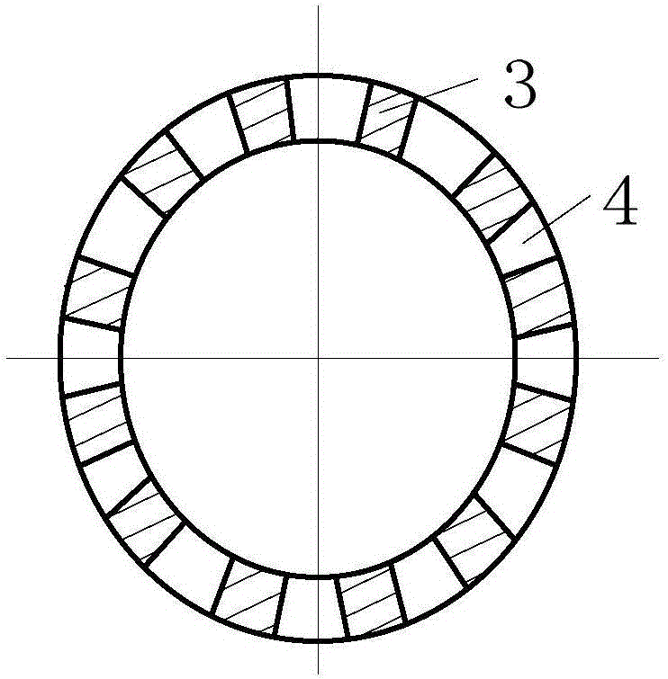
[0030] Such as Figure 2-4 As shown, the rotating cylinder includes an upper rotating sleeve 3 and a lower rotating sleeve 4; the bottom end surface of the upper rotating sleeve 3 is provided with a plurality of first protrusions arranged at intervals along the circumferential direction. The top end surface of the low...


PUM


Abstract

The invention discloses a continuous circulation drilling active sealing type rotation control head and a screw-on-off method thereof. The continuous circulation drilling active sealing type rotation control head comprises a rotating cylinder, a rubber core supporting cylinder and a rubber core cylinder which are arranged in a shell, the rotating cylinder, the rubber core supporting cylinder and the rubber core cylinder are sequentially arranged from outside to inside in a sleeving mode. The inner wall of the rubber core cylinder obliquely protrudes downwards to form a plurality of conical rings used for holding a drill rod to be used as a multi-stage pressure sealing assisting structure, wherein the conical rings are arranged at intervals, and the multi-stage pressure sealing assisting structure is matched with the special structure of the rotating cylinder and the rubber core supporting cylinder to extrude the rubber core cylinder to hold the drill rod to achieve sealing through the hydraulic action. The continuous circulation drilling active sealing type rotation control head is simple and novel in structure, capable of effectively achieving the pressure sealing assistance function and easy to operate; a rubber core is not likely to be abraded and can be used as a drill rod semi-sealing device of a continuous circulation drilling device; a drilling column for sealing rotation is used through cooperation of a multi-gate-plate pressure sealing device, and the continuous circulation screw-on-off function of the drill rod is achieved.

Description


Claims


Application Information

Patent Timeline
Owner BC P INC CHINA NAT PETROLEUM CORP
Learn More