A locking device, its clutch and washing machine

A locking device and a washing machine technology, applied in the field of washing machines, can solve the problems of washing and running, one-way bearing failure, and the impossibility of timely cleaning of friction debris, etc., and achieve the effects of reducing production costs, improving service life, and overcoming the phenomenon of running.

Active Publication Date: 2019-08-30
NINGGUO JULONG IND
View PDF12 Cites 0 Cited by
  • Summary
  • Abstract
  • Description
  • Claims
  • Application Information

AI Technical Summary

Problems solved by technology

[0002] The current non-hand rubbing ordinary washing machine, according to the principle of action force and reaction force, must have a supporting force to push the pulsator and / or the inner tub to rotate. In order to realize the expected power, a locking device is set on the clutch. The locking device is a brake wheel, by setting a brake band and a one-way bearing on the brake wheel, two-way locking the brake wheel to achieve support force, and the free direction of the one-way bearing is the dehydration direction of the washing machine; this brake band and one-way bearing The locked locking device, after the product is installed on the washing machine for a long time, sometimes produces squealing, washing rotation and one-way bearing failure; although people have been trying to optimize the contact surface between the brake band and the brake wheel to eliminate the squealing phenomenon, but this phenomenon is difficult to cure, because after friction, friction debris will definitely be produced, and this friction debris cannot be cleaned in time, and it adheres to the surface of the brake belt and brake wheel. Due to the wear of the friction plate, the braking torque decreases, which is prone to decrease the braking torque, or the failure of the one-way bearing, which will cause the inner bucket to rotate, and the clothes cannot be washed effectively during washing. This is what we need to solve. technical problem

Method used


Image

  • A locking device, its clutch and washing machine
  • A locking device, its clutch and washing machine
  • A locking device, its clutch and washing machine

Examples


Embodiment Construction

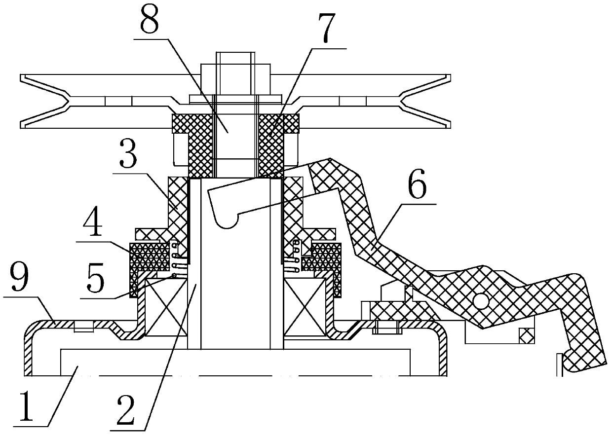
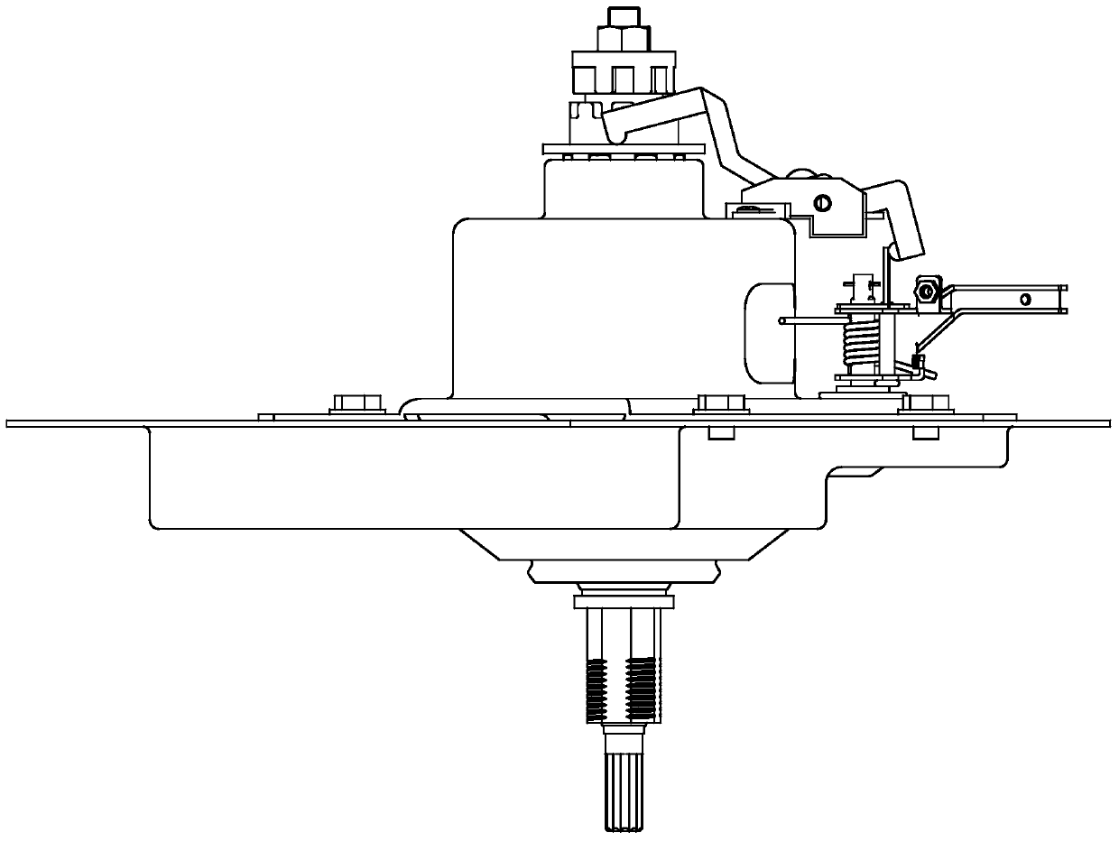
[0032] combine Figure 2-Figure 15 , is a structural schematic diagram of an embodiment of the locking device of the present invention. The locking device includes a brake wheel 1 that is movably installed in the housing 9 in the axial direction. The clutch shaft 2 is fastened to the brake wheel 1 . There is a bearing 11 between them, which is characterized in that: the bearing 11 is a two-way ordinary bearing, the housing 9 is provided with a locking ring 4 connected with it, and the clutch shaft 2 is provided with a The lock sleeve 3 is locked and axially slidably engaged. A movable elastic member 5 is provided on one end surface of the lock sleeve 3 in the axial direction, and a shift fork 6 is movably connected to the other end surface to control its up and down movement.

[0033] More specifically, the clutch shaft 2 and the locking sleeve 3 are connected by splines; the locking ring 4 is arranged inside the housing 9, and the locking ring 4 can also be arranged in the ho...


PUM


Abstract

The invention relates to a locking device, a clutch and a washing machine, and relates to the washing machine technical field, thus solving the technical problems that an existing washing machine has belt noise, washing follow up rotation and unidirectional bearing failure; a housing is provided with a locking ring connected with the housing in one body; a clutch shaft is provided with a locking sleeve radially locked with the clutch and engaged in axial sliding; an input shaft is coaxially arranged in the clutch shaft of the clutch, and provided with a clutch sleeve; a shifting fork is movably arranged on the housing in a rotary manner through a lever fulcrum; when the shifting fork of the washing machine leaves the locking sleeve, the locking sleeve is separated from the locking ring under an elastic part effect, and engaged with the clutch sleeve in one piece; the locking device can improve clutch reliability, can effectively prevent clutch belt noise, can solve the washing machine follow up rotation phenomenon, thus improving washing machine service life, and simultaneously reducing clutch or washing machine production costs.

Description

technical field [0001] The invention relates to the technical field of washing machines, in particular to a locking device for a washing machine clutch. Background technique [0002] The current non-hand rubbing ordinary washing machine, according to the principle of action force and reaction force, must have a supporting force to push the pulsator and / or the inner tub to rotate. In order to realize the expected power, a locking device is set on the clutch. The locking device is a brake wheel, by setting a brake band and a one-way bearing on the brake wheel, two-way locking the brake wheel to achieve support force, and the free direction of the one-way bearing is the dehydration direction of the washing machine; this brake band and one-way bearing The locked locking device, after the product is installed on the washing machine for a long time, sometimes produces squealing, washing rotation and one-way bearing failure; although people have been trying to optimize the contact ...

Claims


Application Information

Patent Timeline
Patent Type & Authority Patents(China)
IPC IPC(8): D06F37/40D06F37/30
Inventor 刘军周国祥李慧玄
Owner NINGGUO JULONG IND
Why Eureka
Try Eureka