
Floating joint and punch applying floating joint

A technology of floating joints and male joints, which is applied in the field of mechanical processing parts, can solve the problems of high processing precision and assembly precision, short service life, high cost, etc., and achieve the effect of high precision, long service life and reasonable structure

Inactive Publication Date: 2017-01-04
CHANGSHA JINGHUA ELECTRONICS TECH
View PDF19 Cites 2 Cited by
  • Summary
  • Abstract
  • Description
  • Claims
  • Application Information

AI Technical Summary

Problems solved by technology

[0003] The traditional floating joint has bearings, springs or other elastic components inside, which cannot withstand high pressure, is easy to wear, has a short service life, and has a complex structure. It requires high machining accuracy and assembly accuracy and is difficult to guarantee, resulting in high costs.

Method used


Image

  • Floating joint and punch applying floating joint
  • Floating joint and punch applying floating joint
  • Floating joint and punch applying floating joint

Examples

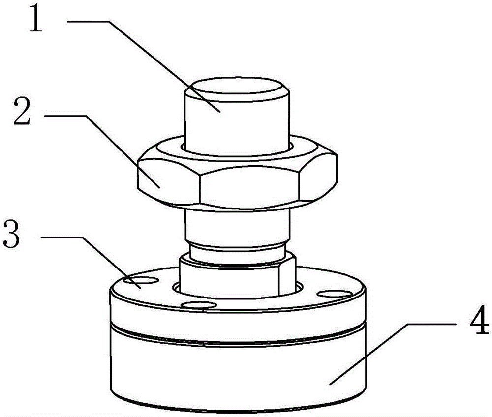
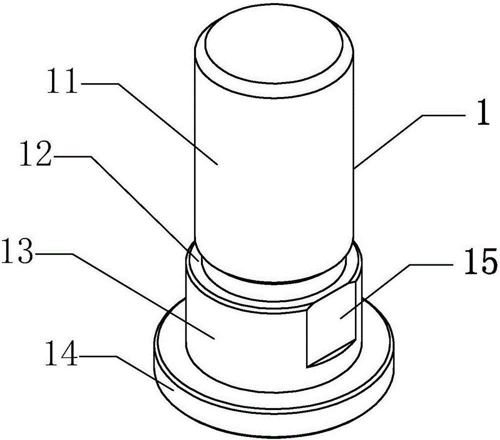

Embodiment Construction

[0025] It should be noted that, in the case of no conflict, the embodiments of the present invention and the features in the embodiments can be combined with each other. The present invention will be described in detail below with reference to the accompanying drawings and examples.

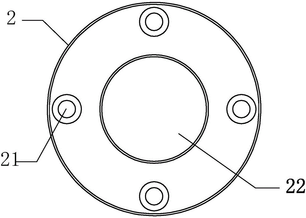
[0026] Combine below Figure 1-Figure 5 , the preferred embodiments of the present invention will be described in further detail.

[0027] This embodiment provides a floating joint, including a male joint 1, a female joint 4 and a cover plate 3. The upper end of the male joint 1 is a connecting end 11, and the lower end is clamped and fixed on the joint formed by connecting the cover plate 3 and the female joint 4. In the cavity, the lower end of the female joint 4 is provided with a connecting structure, and the force transmission is realized through the male joint 1, the cover plate 3 and the female joint 4. Due to the active setting of the male joint 1 and the cavity and the influence of mach...


PUM


Abstract

The invention discloses a floating joint and a punch applying the floating joint. The floating joint comprises a male joint, a female joint and a cover plate, wherein the upper end of the male joint is a connecting end; the lower end of the male joint is fixedly clamped in a cavity formed by connecting the cover plate and the female joint; the lower end of the female joint is provided with a connecting structure. The floating joint is reasonable in structure; punching and necking are performed on components, so that high accuracy and easiness in machining can be realized easily, radial errors, axial errors and angular errors within certain ranges can be corrected, the axial length can be adjusted, and high adaptability is achieved. The characteristic of the presence of a bearing, a spring or other elastic structures in the conventional floating joint is abandoned; a novel flexible connecting structure is adopted, so that assembly errors are eliminated, and higher pressure can be borne at the same time; the floating joint has the advantages of little wear, long service life, reliable structure, high tensile strength, high compression resistance and the like.

Description

technical field [0001] The invention belongs to the technical field of machining components, and relates to a mechanical connection device. Background technique [0002] The function of the floating joint is to connect two shafts in different mechanisms, the driving shaft and the driven shaft, so that they rotate together to transmit torque. The second is to eliminate errors, especially in some high-speed and heavy-load environments, the output of the power mechanism is relatively large. If the direction of the force and the point of force are not on the same line when the power mechanism is extended, the shaft rod is easy to deform , One end of the floating joint is floating, which can be used to absorb or correct the lateral force, to achieve flexible connection, even if there are some dimensional deviations, it is not a big problem, to protect related components and make the equipment run smoothly, and to prolong the service life of the equipment. [0003] The traditiona...

Claims


Application Information

Patent Timeline
Patent Type & Authority Applications(China)
IPC IPC(8): B21D37/12
CPCB21D37/12
Inventor 邓晓红罗朝辉
Owner CHANGSHA JINGHUA ELECTRONICS TECH
Learn More