
Hydraulic manipulator of rolling mill

A hydraulic and rolling mill technology, which is applied in the field of centering equipment, can solve problems such as wear, complex structure, and damage of push rods, and achieve the effects of reducing the probability of failure, good overall rigidity, and a good working environment

Inactive Publication Date: 2017-01-04
CERI TECH +1
View PDF7 Cites 3 Cited by
  • Summary
  • Abstract
  • Description
  • Claims
  • Application Information

AI Technical Summary

Problems solved by technology

Although the structure has reliable synchronization performance, the structure is complex and inconvenient to maintain
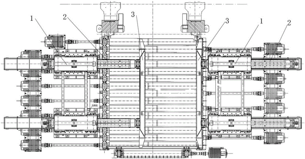
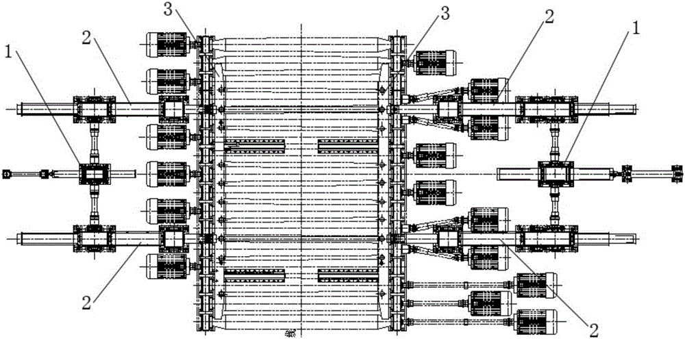
[0005] In order to simplify the structure and facilitate maintenance, a pusher is proposed in the prior art, such as Figure 5 , Image 6 As shown, each side of the push bed is driven by a hydraulic cylinder 1, and the hydraulic cylinder 1 is arranged between two push rods 2, and the push rods 2 on the same side are connected together by a beam to realize synchronization, and the supporting wheels and side guide wheels are installed on the On the open bracket, the above-mentioned structure is simple, easy to maintain, and reduces the number and cost of parts. However, compared with the previous two types of push beds that use synchronous shafts to achieve synchronization, the push rod of the third type of push bed is 2 The stiffness of the guide wheel bracket and the working environment of the guide wheel are poor. During use, due to the insufficient overall rigidity, it is often easy to cause deformation and damage to the guide wheel and the push rod 2. The poor working environment is also easy to cause the guide wheel to be damaged. And the wear of the push rod 2 will eventually cause the synchronization of the two push rods to decline, and even stop production for replacement

Method used


Image

  • Hydraulic manipulator of rolling mill
  • Hydraulic manipulator of rolling mill
  • Hydraulic manipulator of rolling mill

Examples


Embodiment Construction

[0041] The details of the present invention can be understood more clearly with reference to the accompanying drawings and the description of specific embodiments of the present invention. However, the specific embodiments of the present invention described here are only for the purpose of explaining the present invention, and should not be construed as limiting the present invention in any way. Under the teaching of the present invention, the skilled person can conceive any possible modification based on the present invention, and these should be regarded as belonging to the scope of the present invention.

[0042] Please refer to Figure 7 to Figure 10 , Figure 7 It is a structural schematic diagram of the rolling mill hydraulic push bed proposed by the present invention; Figure 8 The top view of the rolling mill hydraulic push bed proposed by the present invention; Figure 9 for Figure 7 The cross-sectional view of A-A direction in the middle; Figure 10 for Figur...


PUM


Abstract

The present invention provides a hydraulic manipulator of a rolling mill, and relates to a centering apparatus for use in front and rear of the rolling mill. The hydraulic manipulator of the rolling mill comprises two pushing units provided on two sides of a rolling line, and each pushing unit comprises a push plate. A moving frame is in a horizontal state and comprises two push rods and at least one connecting beam, and one end of each push rod is connected to the other end of the push plate and extends in a direction perpendicular to the rolling line and away from the rolling line. Space is reserved between the push rods. The connecting beam is connected between the two push rods, each of which is provided with at least one guide means. The guide means at least comprises a guide wheel support, the guide wheel support is a box body having a mounting cavity, the push rods penetrate a mounting chamber in the horizontal direction, a wheel and a side guide wheel are installed in the mounting chamber, the wheel is in rolling contact with the bottom surfaces of the push rods, the side guide wheel is in rolling contact with the outer sides of the push rods. A hydraulic cylinder is arranged between the two push rods. The hydraulic cylinder drives the moving frame to reciprocate.

Description

technical field [0001] The invention relates to a centering device used for front and rear of a rolling mill, in particular to a rolling mill hydraulic pusher used for a hot-rolled thick plate production line. Background technique [0002] At present, the pushing beds used in the front and back of the plate rolling mill on the hot rolling production line generally adopt the form of a rack and pinion driven by a hydraulic drive cylinder. Such as figure 1 , two hydraulic cylinders 1 are used to drive two push rods 2 on each side of the transmission side and the operation side, and the push plate 3 is arranged perpendicular to the push rod 2 and hung on the head of the push rod 2 through the pin shaft, so as to realize the push rod 3 open and closed. The two push rods 2 on the same side are mechanically synchronized by the synchronous shaft through the rack and pinion, and the push rods 2 on the opposite side are synchronized by the displacement sensor inside the hydraulic cy...

Claims


Application Information

Patent Timeline
IPC IPC(8): B21B39/14
CPCB21B39/14
Inventor 马振海徐永华周西康高学文任际军苏洸刘延军杨邵伟
Owner CERI TECH
Learn More