
Ultrafiltration membrane assembly of porous water inlet pipe

A water inlet pipe, ultrafiltration membrane technology, applied in ultrafiltration, membrane technology, semi-permeable membrane separation and other directions, can solve problems such as increased energy consumption, decreased water flux, pollution, etc., to reduce replacement costs and prolong use. Longevity, the effect of reducing the frequency of cleaning

Inactive Publication Date: 2017-01-04
SHANDONG MEM RESOURCE WATER PURIFICATION TECH
View PDF5 Cites 3 Cited by
  • Summary
  • Abstract
  • Description
  • Claims
  • Application Information

AI Technical Summary

Problems solved by technology

During the use and operation of the traditional monolithic ultrafiltration membrane module, since the hollow fiber ultrafiltration membrane used in the ultrafiltration membrane module belongs to microporous filtration, it is easily polluted by impurities in water during operation, thereby blocking the micropores and causing the water to pass through. The amount is reduced, thereby increasing the energy consumption of the operation
In addition, due to the uneven distribution of water, the hollow ultrafiltration membranes are easily polluted, resulting in a decrease in the permeation flux of the membranes, and even making the membrane modules unusable, and the cleaning is also difficult, which hinders their widespread use in actual development. application
Due to uneven water distribution, uneven pollution results, which shortens the service life of the ultrafiltration membrane stack

Method used


Image

  • Ultrafiltration membrane assembly of porous water inlet pipe
  • Ultrafiltration membrane assembly of porous water inlet pipe

Examples


Embodiment Construction

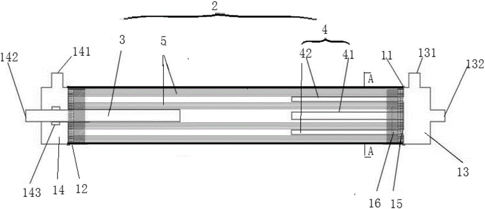
[0014] Such as figure 1 As shown, the ultrafiltration membrane assembly of the porous water inlet pipe in this embodiment includes a pressure-bearing housing 1 and an ultrafiltration membrane group 2 , and the ultrafiltration membrane group 2 is arranged in the pressure-bearing housing 1 . The ultrafiltration membrane group 2 specifically includes an outlet pipe 3 , an inlet pipe 4 and hollow fiber ultrafiltration membrane filaments 5 . The water inlet port 11 of the pressure-bearing shell 1 is covered with a water inlet end cover 13, and the water outlet port 12 is covered with a water outlet end cover 14. The water inlet end cover 13 is provided with a raw water inlet and an aeration device 132, and the water outlet end cover 14 is provided with a clean water outlet 141 and a concentrated water outlet 142, and the concentrated water outlet 142 is connected to the outlet pipe 3 through a pipeline. During specific implementation, the water inlet end cover 13 and the water out...


PUM


Abstract

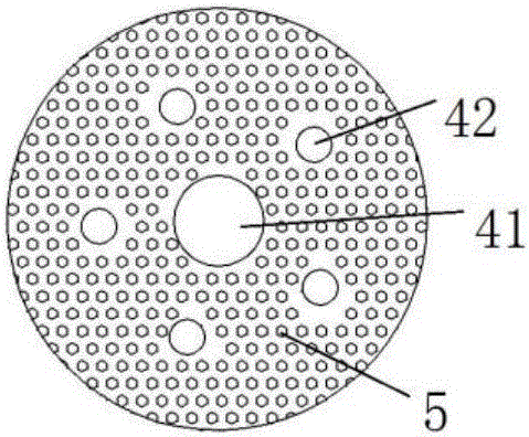
The invention discloses an ultrafiltration membrane assembly of a porous water inlet pipe. The ultrafiltration membrane assembly comprises a pressure-bearing shell and an ultrafiltration membrane group which is arranged in the pressure-bearing shell, the ultrafiltration membrane group particularly comprises a water outlet pipe, water inlet pipes and hollow fiber ultrafiltration membrane silk, the water inlet pipes are fixed to a water inlet port of the pressure-bearing shell, the water outlet pipe is fixed to a water outlet port of the pressure-bearing shell, the two ends of the hollow fiber ultrafiltration membrane silk are fixed to the water inlet port and the water outlet port respectively, hard rubber and soft rubber are poured into the water inlet port and the water outlet port of the pressure-bearing shell so as to fill reserved gaps of the water pipe; the water inlet pipe particularly comprises one central water inlet pipe and multiple outer side water inlet pipes, the central water inlet pipe is arranged on the central position of the pressure-bearing shell, the outer side water inlet pipes are arranged surrounding the central water inlet pipe, the central water inlet pipe and the outer side water inlet pipe are provided with multiple holes, and the total area of the holes formed in each water inlet pipe is 1.5 times to 2.5 times the area of the cross section of the water inlet pipe. The ultrafiltration membrane assembly is uniform in water distribution, not prone to pollute a module and easy to clean.

Description

technical field [0001] The invention relates to a filtering device, in particular to an ultrafiltration membrane assembly of a porous water inlet pipe. Background technique [0002] In recent years, with the continuous development of industrialization, water pollution has become more and more serious. According to the World Health Survey, 80% of the diseases in the world are related to the poor quality of drinking water. Today, with the significant improvement of living standards, people have higher and higher requirements for water treatment. Therefore, more and more enterprises choose ultrafiltration for water treatment. Ultrafiltration is a membrane separation technology that can purify and separate solutions. The ultrafiltration membrane group is a solution separation device with ultrafiltration membrane silk as the filter medium and the pressure difference on both sides of the membrane as the driving force. The ultrafiltration membrane can allow solvents (such as wat...

Claims


Application Information

Patent Timeline
IPC IPC(8): B01D61/18B01D63/02B01D65/02C02F1/44
CPCB01D61/18B01D61/145B01D63/025B01D65/02B01D2321/18C02F1/444
Inventor 张友思孔文张勇黄永福刘凯李炜
Owner SHANDONG MEM RESOURCE WATER PURIFICATION TECH
Learn More