
Finite array antenna analysis method

An array antenna and analysis method technology, applied in the field of finite array antenna analysis, can solve problems such as high simulation time requirements, optimal design, unfavorable arrays, etc. Effect

Active Publication Date: 2016-12-28
CHINA SHIP DEV & DESIGN CENT
View PDF7 Cites 5 Cited by
  • Summary
  • Abstract
  • Description
  • Claims
  • Application Information

AI Technical Summary

Problems solved by technology

However, once the scale of the array is too large, limited by the current computing power, using the above methods will take a lot of simulation time and have high requirements for the simulation hardware, and sometimes it cannot even be calculated. Even if it can be solved, the simulation time is too long. Not conducive to optimal design of the array
[0004] Another analysis method that considers mutual coupling is to use the analysis method of infinite periodic structure. Although the problem of infinite periodic structure is transformed into the solution of a single antenna through the Floquet theorem, the mutual coupling effect between antennas is considered, and the numerical solution is less computationally intensive. The simulation time is less, but the finite array is considered as an infinite periodic structure, and the edge effect and truncation effect of the array are ignored. The accuracy is determined by the size of the array and the influence of the edge effect. Under the condition of array resonance, the error is very large

Method used


Image

  • Finite array antenna analysis method
  • Finite array antenna analysis method
  • Finite array antenna analysis method

Examples


Embodiment Construction

[0028] In order to make the object, technical solution and advantages of the present invention more clear, the present invention will be further described in detail below in conjunction with the examples. It should be understood that the specific embodiments described here are only used to explain the present invention, not to limit the present invention.

[0029] A finite array antenna analysis method, comprising the following steps:

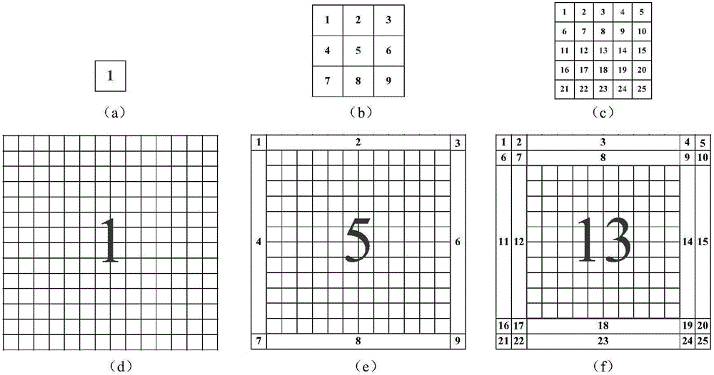
[0030] (A) Determine the sub-array solution scale according to the solution accuracy

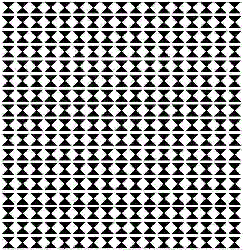
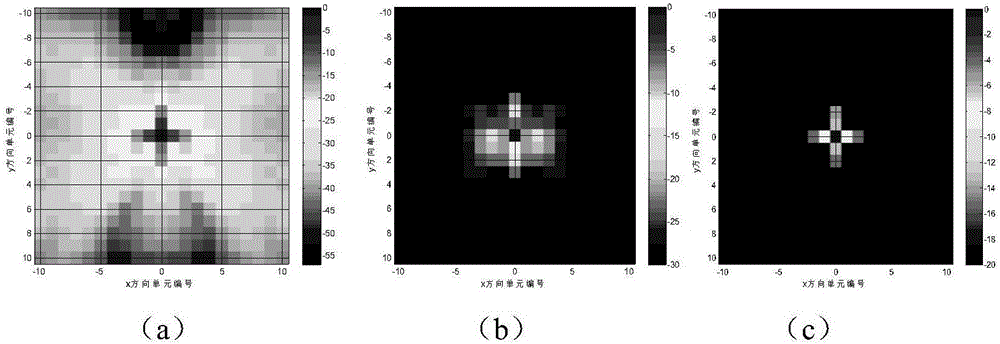
[0031] For medium and large antenna arrays (the number of array elements is greater than 1000), design a small array with the same topology (tens to hundreds of array elements), feed the central unit, and use the method of moments (or multi-layer fast multipole Sub) solution, the antenna array model such as figure 1 As shown, the surface current distribution of the antenna array obtained by simulation is as follows: figure 2 As shown in a, define the rela...


PUM


Abstract

The invention discloses a finite array antenna analysis method. The method includes the following steps that the subarray solving scale is determined according to solving precision; full-wave solving is carried out on determined subarrays with a moment method; medium and large arrays are extrapolated according to the subarray solving result; in the process of solving subarray radiation fields, the subarray radiation fields are assumed to be radiation far fields, and an array antenna pattern is obtained. According to the method, based on the local effect of array antenna unit radiation fields and the electromagnetic field superposition principle, the numerical simulation issue of medium and large array antennas is simplified into full-wave solving of the subarrays according to the solving precision, then all unit radiation fields in the large arrays are equivalent to the unit radiation fields at corresponding positions in the subarrays, and finally based on the superposition theorem, the total radiation field is calculated, so that full-array matrix filling and the operation of solving the system of linear equations in the calculation process are omitted; besides, the radiation field calculation issue of the large arrays is transformed into the unit radiation field calculation issue of the small arrays, so that the calculation amount is effectively reduced, and the implementation difficulty is lowered.

Description

technical field [0001] The invention relates to electromagnetic compatibility technology, in particular to a method for analyzing a finite array antenna. Background technique [0002] Due to the high cost of medium and large array antennas, accurate simulation predictions of radiation patterns, radiation near and far fields, standing waves, and scanning characteristics mean less design risk and cost waste, which can reduce the workload of experimental adjustments, improve R&D progress and save manpower and material resources. At the same time, a correct and effective evaluation of the unit mutual coupling is helpful to understand the characteristics of the array antenna and guide the actual design work. Therefore, it is particularly important to find an accurate simulation analysis of medium and large arrays. [0003] The mutual coupling of array elements in medium and large arrays will deteriorate the performance of the pattern, and the antenna sidelobe level will become ...

Claims


Application Information

Patent Timeline
IPC IPC(8): G06F17/50G06F17/12
CPCG06F17/12G06F30/20
Inventor 吴锋涛张凯
Owner CHINA SHIP DEV & DESIGN CENT
Learn More