
Remotely-detectable emergency lighting and evacuation indication system

An emergency lighting and remote technology, applied in the field of emergency lighting, can solve problems such as collective panic, large-scale stampede, and complex internal structure, and achieve the effects of improving management efficiency, realizing remote detection, and realizing unified management

Inactive Publication Date: 2016-12-21
合肥联信电源有限公司
View PDF7 Cites 4 Cited by
  • Summary
  • Abstract
  • Description
  • Claims
  • Application Information

AI Technical Summary

Problems solved by technology

[0002] With the rapid development of the city, there are more and more large-scale public buildings with complex internal structures and dense population. If there is no timely and correct evacuation guidance in the event of a fire, a large number of people will be stranded at the fire scene, which may cause collective disasters. Panic, which in turn led to a large-scale stampede, resulting in tragic scenes of mass death and mass injury
[0003] Traditional evacuation systems mostly use non-centralized power supply and non-centralized control systems. Each evacuation indicator light works independently, with a single direction, and cannot perform dynamic indication. This has the risk of guiding people to the fire scene, and the lamps cannot perform self-inspection, which may Causes the evacuation lights to fail to work in the event of a fire
[0004] To sum up, the traditional emergency evacuation system cannot monitor each terminal product in real time from a distance, and cannot point out the effective evacuation safety network for the affected people in time of disaster.

Method used


Image

  • Remotely-detectable emergency lighting and evacuation indication system

Examples


Embodiment Construction

[0026] The following will clearly and completely describe the technical solutions in the embodiments of the present invention with reference to the accompanying drawings in the embodiments of the present invention. Obviously, the described embodiments are only some, not all, embodiments of the present invention. Based on the embodiments of the present invention, all other embodiments obtained by persons of ordinary skill in the art without creative efforts fall within the protection scope of the present invention.

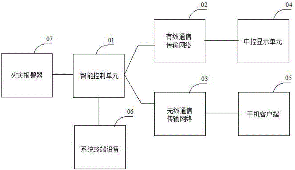
[0027] see figure 1 As shown, the present invention is a remotely detectable emergency lighting and evacuation indication system, including an intelligent control unit 01, connected with a fire alarm 07 and a system terminal device 06, and the intelligent control unit 01 performs data interaction with the system terminal device 06, The system terminal device 06 is a smart phone or a computer or a tablet; the intelligent control unit 01 also includes a central proce...


PUM


Abstract

The present invention discloses a remotely-detectable emergency lighting and evacuation indication system. The system includes an intelligent control unit, a data transmission unit, a centralized control display unit and a mobile phone client type; the intelligent control unit is connected with a fire alarm and a system terminal device; the intelligent control unit carries out data interaction with the system terminal device; the data transmission unit is used for the intelligent control unit to transmit data; and the central control display unit and the mobile phone client are used for displaying the data of the intelligent control unit. The remotely-detectable emergency lighting and evacuation indication system is a centralized control type intelligent fire emergency lighting and evacuation system, can communicate with a fire automatic alarm system, and receives the alarm position information of the fire alarm system; the host of the evacuation indication system automatically generates an optimal evacuation line according to an alarm point, so that people can be guided to evacuate rapidly along a safe passage through a safe exit; and the remote detection of the intelligent evacuation indication system can be realized effectively, so that unified management and resource integration can be realized, and management efficiency can be improved.

Description

technical field [0001] The invention belongs to the technical field of emergency lighting, in particular to a remotely detectable emergency lighting and evacuation indicating system. Background technique [0002] With the rapid development of the city, there are more and more large-scale public buildings with complex internal structures and dense population. If there is no timely and correct evacuation guidance in the event of a fire, a large number of people will be stranded at the fire scene, which may cause collective disasters. Panic, which in turn led to a large-scale stampede, resulting in tragic scenes of mass death and mass injury. [0003] Traditional evacuation systems mostly use non-centralized power supply and non-centralized control systems. Each evacuation indicator light works independently, with a single direction, and cannot perform dynamic indication. This has the risk of guiding people to the fire scene, and the lamps cannot perform self-inspection, which ...

Claims


Application Information

Patent Timeline
Patent Type & Authority Applications(China)
IPC IPC(8): H05B37/02
CPCH05B47/105H05B47/18H05B47/19Y02B20/40
Inventor 李多山李青
Owner 合肥联信电源有限公司
Learn More