Low-voltage integrated distribution box

A distribution box, low-voltage technology, applied in electrical components, substation/switch layout details, substation/switchgear cooling/ventilation, etc. The problem of poor rainproof performance, etc., can save the cost of centralized copying and maintenance, save the cost of centralized copying and maintenance, and have strong installation and mobile performance.

Inactive Publication Date: 2016-09-07
NANJING YALI ELECTRICAL
View PDF9 Cites 3 Cited by
  • Summary
  • Abstract
  • Description
  • Claims
  • Application Information

AI Technical Summary

Problems solved by technology

[0002] The existing integrated distribution box has a small space inside the shell, and the installation of the components is relatively compact, which is easy to cause heat; the size and installation method of each box are different, the cable connection is complicated and tortuous, and the installation is inconvenient; there is no installation of capacitance compensation inside Space; the air circulation with the outside world is not smooth, which is likely to cause tripping; there is no remote detection and remote control function; the seat and hoisting brackets are not universal, and it is inconvenient to move the distribution box; the rainproof performance of the louvered windows is not good, and it is easy to It will cause the switch to be damp and water to accumulate in the cabinet, which poses a great threat to personal safety.
[0003] In addition, the publication number is an invention patent of CN203521947 U, which discloses a multifunctional integrated distribution box, including a distribution box body and a distribution box base, and several bases are arranged on both sides of the distribution box body, and the upper layer A water-absorbing resin layer is set between the base and the lower base, but the structure of the scheme is complicated, and the comprehensive utilization rate of the distribution box is low

Method used


Image

  • Low-voltage integrated distribution box
  • Low-voltage integrated distribution box
  • Low-voltage integrated distribution box

Examples


Embodiment Construction

[0024] The present invention will be described in further detail below in conjunction with the accompanying drawings.

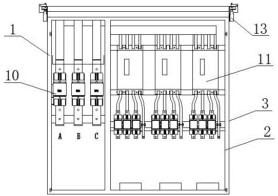
[0025] refer to figure 1 .

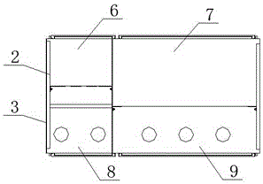
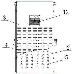
[0026] A low-voltage integrated distribution box, including a box shell 1, the box shell 1 is divided into four working rooms, which are respectively a metering room 6, a capacitance compensation room 7, an incoming line room 8 and an outgoing line room 9. A residual current operated circuit breaker 10 is provided inside the metering chamber 6, a fuse 3 is provided inside the capacitance compensation chamber 7, an inner panel 2 and an outer panel 3 are provided on the left and right sides of the housing 1, and the inner panel 2 is provided with A first ventilation hole 5 is provided, and a second ventilation hole 4 is provided on the outer plate 3 .

[0027] The diameter of the second ventilation hole 4 is larger than that of the first ventilation hole 5 , and the first ventilation hole 5 and the second ventilation hole 4 are st...


PUM


Abstract

The present invention relates to a low-voltage integrated distribution box, belonging to the technical field of electric equipment. The low-voltage integrated distribution box includes a box shell. The interior of the box shell is separated into four working rooms, including a measuring room, a capacitance compensation room, a cable entry room and a cable exit room. The measuring room is internally provided with a residual current operated circuit breaker. The capacitance compensation room is internally provided with a fuse. Both the left side surface and the right side surface of the shell are provided with an inner panel and an outer panel. The inner panel is provided with a first air vent, and the outer panel is provided with a second air vent, thereby promoting air circulation between interior and exterior of the box, and lowering interior temperature of the box. The box is more convenient to install and move, less rainwater enters the box, and the protection level of the box is improved.

Description

technical field [0001] The invention relates to a low-voltage integrated distribution box, which belongs to the technical field of electric equipment. Background technique [0002] The existing integrated distribution box has a small space inside the shell, and the installation of the components is relatively compact, which is easy to cause heat; the size and installation method of each box are different, the cable connection is complicated and tortuous, and the installation is inconvenient; there is no installation of capacitance compensation inside Space; the air circulation with the outside world is not smooth, which is likely to cause tripping; there is no remote detection and remote control function; the seat and hoisting brackets are not universal, and it is inconvenient to move the distribution box; the rainproof performance of the louvered windows is not good, and it is easy to It will cause the switch to be damp and the cabinet to accumulate water, which poses a gre...

Claims


Application Information

Patent Timeline
Patent Type & Authority Applications(China)
IPC IPC(8): H02B1/56H02B1/46H02B1/48
CPCH02B1/565H02B1/46H02B1/48
Inventor 严基伟
Owner NANJING YALI ELECTRICAL
Why Eureka
Try Eureka