
A control method, device and system for a power network

A technology of power network and control method, applied in the field of power, can solve problems such as large demand and low utilization rate of production capacity equipment

Active Publication Date: 2018-11-30
ENN SCI & TECH DEV
View PDF6 Cites 0 Cited by
  • Summary
  • Abstract
  • Description
  • Claims
  • Application Information

AI Technical Summary

Problems solved by technology

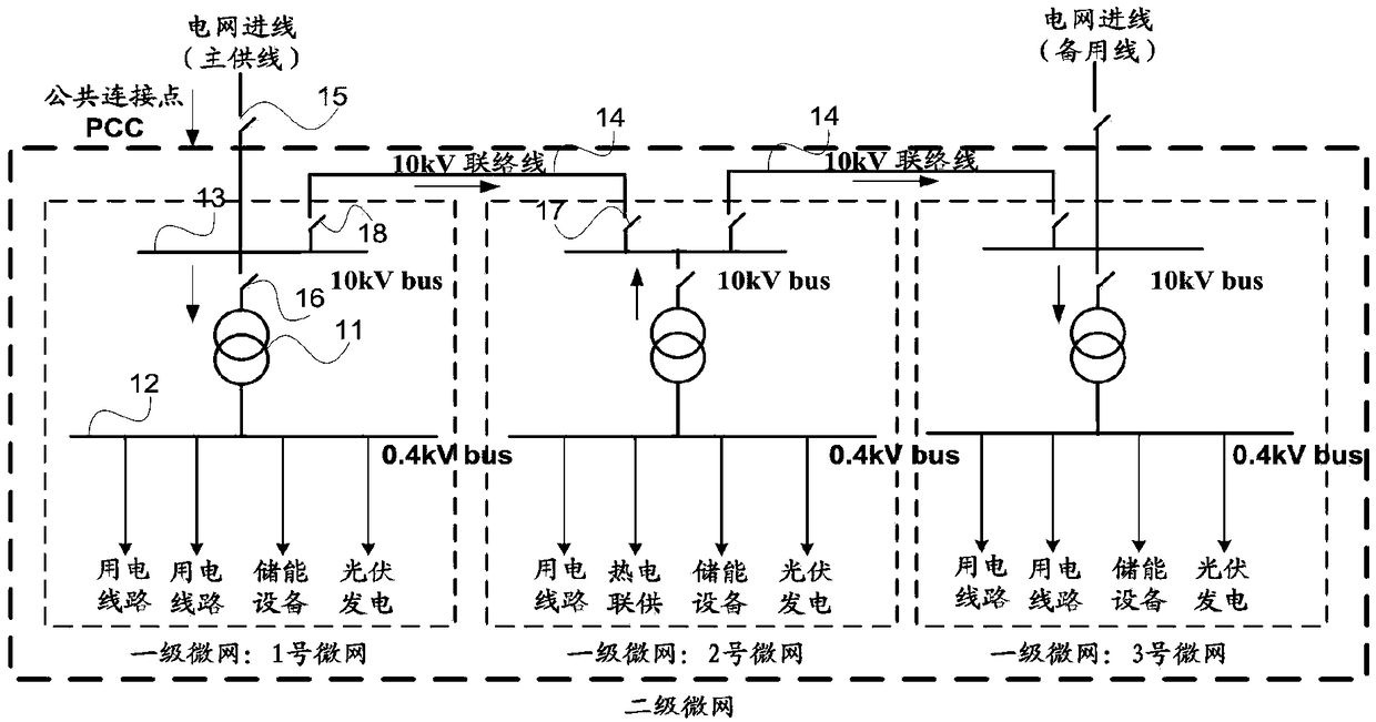
[0005] Embodiments of the present invention provide a method, device, and system for controlling a power network, in order to improve the problem of low utilization rate of production equipment or grid-connected micro-grid in the prior art in order to meet the supply and demand balance of grid-connected micro-grid To solve the problem of large demand on the power grid, a new power network is provided, and a control scheme for micro-grid power in the power network is provided

Method used


Image

  • A control method, device and system for a power network
  • A control method, device and system for a power network
  • A control method, device and system for a power network

Examples


Embodiment 1

[0092] An embodiment of the present invention provides a control method for the above electric power network, refer to Figure 6 As shown, the specific steps include:

[0093] S601 (optional). The network scheduling device receives the real-time operating parameters of the microgrid sent by each microgrid control device in the microgrid group.

[0094] Wherein, the real-time operation parameters of the microgrid include: the real-time power parameters of the grid-connected point of the microgrid, and the power increase capability and power reduction capability of the microgrid. The real-time power parameters of the grid-connected point of the microgrid may include one or more of active power, reactive power, power factor, voltage and current of the grid-connected point of the microgrid. The real-time power parameter is used to calculate the real-time power value, and the real-time power value is the active power value of the grid-connected point of the microgrid. For example...

Embodiment 2

[0112] This embodiment provides a method for controlling a power network, wherein the power network is the same as the above-mentioned power network.

[0113] The following are specific steps of a method for controlling a power network provided by an embodiment of the present invention, refer to Figure 7 .

[0114] S701 (optional): The micro-grid control device sends real-time operating parameters of the micro-grid controlled by the micro-grid control device to the network scheduling device.

[0115] example, with Figure 5 For example, at this time, the No. 1 micro-grid control device sends the real-time operating parameters of No. 1 micro-grid to the network scheduling device, the No. 2 micro-grid control device sends the real-time operating parameters of No. The device sends the real-time operating parameters of No. 3 microgrid to the network scheduling device.

[0116] Correspondingly, the network scheduling device can obtain the allowable power operation range of each...

Embodiment 3

[0164]An embodiment of the present invention provides a network scheduling device for use in a power network. The power network is the above-mentioned power network. The device can be software or hardware. The implementation of each functional module can refer to the first embodiment above. Here No longer. Such as Figure 10 As shown, the device includes:

[0165] The obtaining unit 101 is configured to obtain the allowed power operation interval of each microgrid in the microgrid group, and the power operation interval includes: the maximum reverse power parameter and the maximum forward power parameter of the grid-connected point of the microgrid;

[0166] The sending unit 102 is configured to send the allowed power operation range of each microgrid to the microgrid control device of the microgrid, so that the microgrid control device can control the real-time power of the grid-connected point of the microgrid to be within the specified range. within the allowable power op...


PUM


Abstract

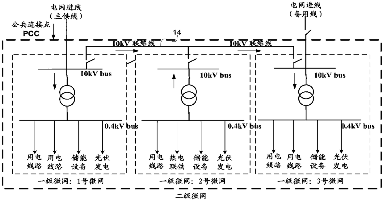
Embodiments of the present invention disclose a control method, device and system for an electric power network, which relate to the field of electric power and are used to improve the problem of low utilization rate of production capacity equipment in the prior art in order to meet the supply and demand balance of grid-connected microgrids or The grid-connected microgrid has a large demand for the power grid. The method includes: the power network includes: N micro-grids, each micro-grid is connected with at least one other micro-grid in the N micro-grids through a tie line, a tie-line switch is arranged on the tie line, and the N micro-grids are divided into M In the microgrid group, the microgrids in each group are connected through tie lines, and each microgrid group is connected with the power supply line of the power grid through a common connection point PCC; for each microgrid group, the network scheduling device obtains each microgrid in the microgrid group. The allowable power operation interval of the grid is sent to the microgrid control device of each microgrid, so that the microgrid control device controls the real-time power of the microgrid grid connection point to be within the allowable power operation interval.

Description

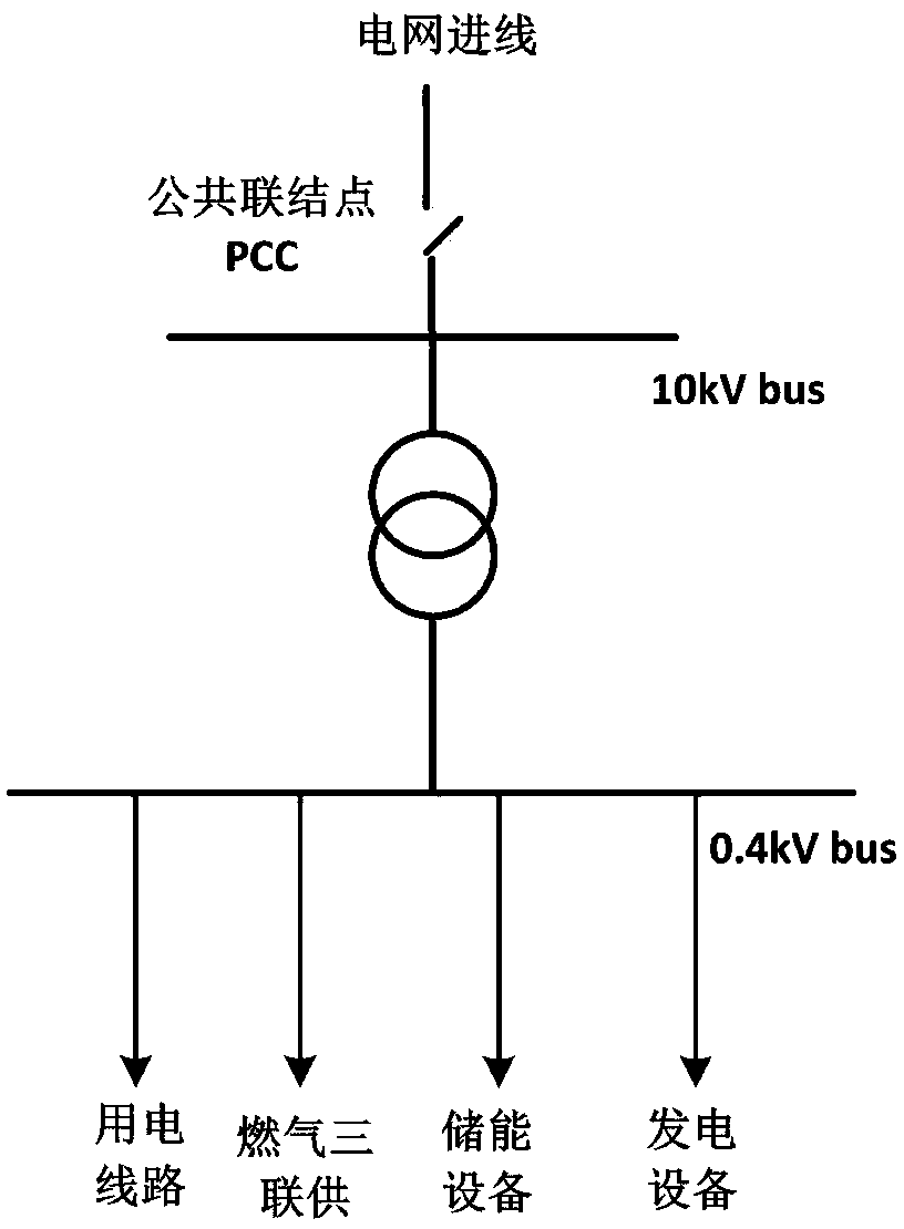
technical field [0001] The invention relates to the field of electric power, in particular to a control method, device and system for a power network. Background technique [0002] Due to its high efficiency, cleanliness, and flexibility, distributed energy can complement traditional energy sources. Micro-grid, also known as micro-grid and micro-grid, is an important utilization method of distributed energy. It is a system mainly composed of load and production equipment (mainly including distributed power generation equipment). A microgrid can either be connected to an external grid or run in isolation. [0003] refer to figure 1 As shown, the microgrid running in parallel with the grid is a grid-connected microgrid, which is characterized by internal production equipment and loads, and the grid through a public connection point (also called a public connection point, which can be referred to as PCC: point of common coupling) connected. [0004] The grid-connected micro...

Claims


Application Information

Patent Timeline
Patent Type & Authority Patents(China)
IPC IPC(8): H02J3/38H02J3/32H02J3/06
CPCH02J3/06H02J3/32H02J3/38
Inventor 舒鹏刘梦琼李龙彬
Owner ENN SCI & TECH DEV
Learn More