


Quick Research
Generate reliable direction feasibility study reports for your R&D in just a few steps.

Technical Q&A
Discover and master advanced knowledge NOW. Basics, ideas, possibilities, all at once.

Find Solutions
As an expert in R&D theories, this can generate solutions to your technical problems instantly.

Evaluate Feasibility
Analyze your overall solution with one click, know your potential R&D risks in advance.

Monitor Landscape
Get weekly tech updates, stay abreast of the latest tech innovations and key insights.
Camera lens and camera device
A camera lens, lens technology, applied in optical components, instruments, optics, etc., can solve the problem of small shooting magnification, and achieve the effect of large shooting magnification
- Summary
- Abstract
- Description
- Claims
- Application Information
AI Technical Summary
Problems solved by technology
Method used
Image

Examples
Embodiment 1
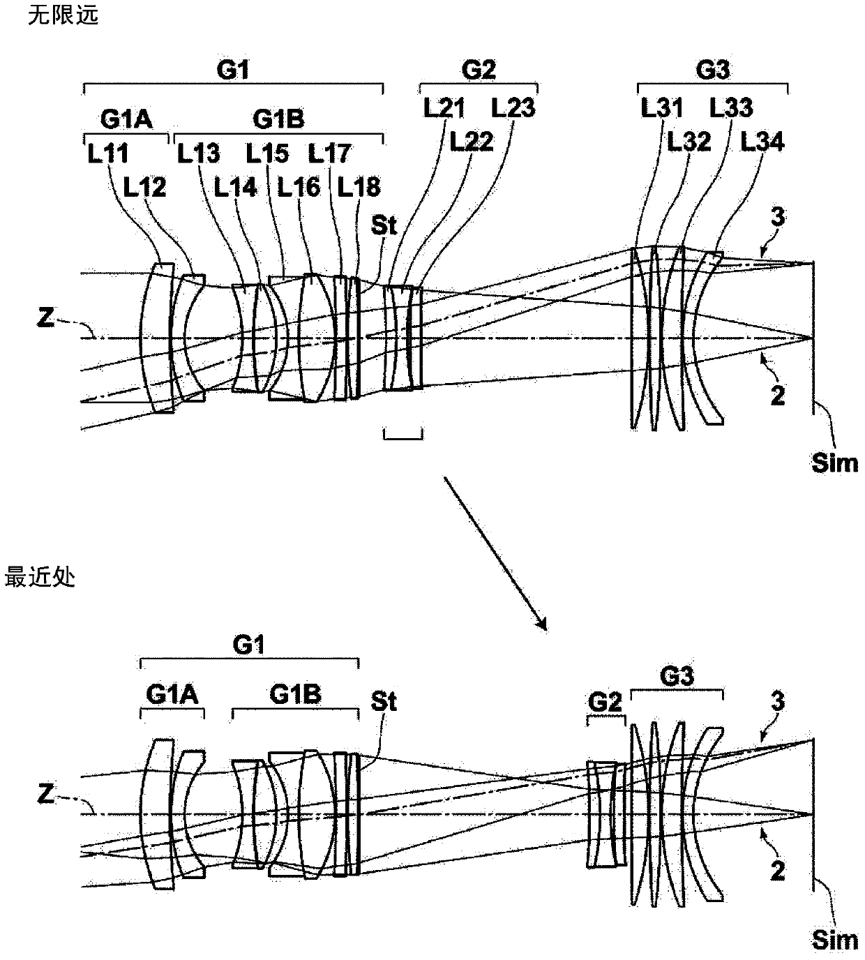
[0192] figure 1 The lens structure and the optical path of the imaging lens of Example 1 are shown, and the method of illustration is as described above, so repeated descriptions are omitted here. The imaging lens of Example 1 is composed of, in order from the object side, a first lens group G1 having positive refractive power, an aperture stop St, a second lens group G2 having negative refractive power, and a third lens group having positive refractive power G3 composition. The focusing group is only the second lens group G2, and when focusing from an object at infinity to the closest object, the second lens group G2 moves to the image side. It should be noted that the three-group structure mentioned here, the sign of the refractive power of each lens group, and the method of focusing are the same for the imaging lenses of Examples 2 to 6 to be described later.
[0193] In the imaging lens of Example 1, the first lens group G1 is composed of a first lens group front group G...
Embodiment 2
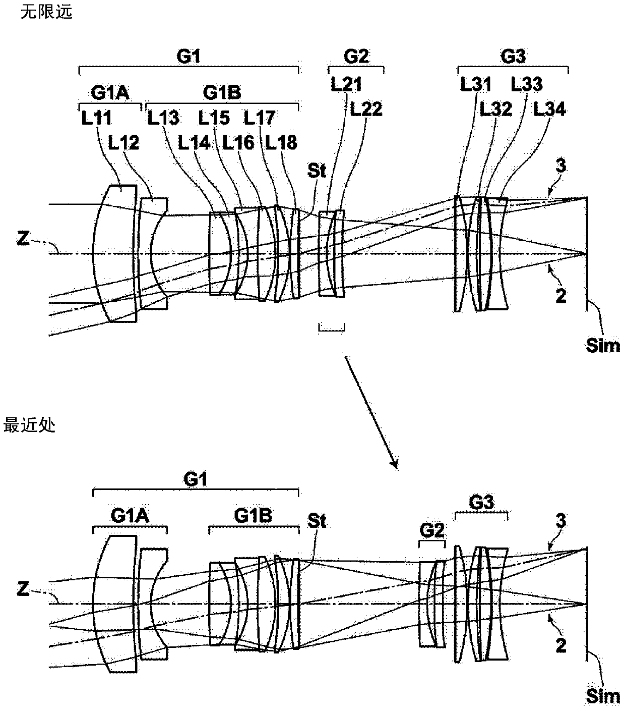
[0217] figure 2 The lens structure and optical path of the imaging lens of Example 2 are shown. In the imaging lens of Example 2, the first lens group G1 is composed of a first lens group front group G1A and a first lens group rear group G1B in order from the object side, and the first lens group front group G1A is composed of, in order from the object side, Lenses L11 to L12 are composed of two lenses, the rear group G1B of the first lens group is composed of six lenses L13 to L18 in order from the object side, and the second lens group G2 is composed of two lenses L21 to L22 in order from the object side The third lens group G3 is composed of four lenses, lenses L31 to L34, in order from the object side. Table 4 shows basic lens data of the imaging lens of Example 2, Table 5 shows aspheric coefficients, and Table 6 shows various factors and values of variable surface spacing. Figure 8 Aberration diagrams of the imaging lens of Example 2 are shown.
[0218] 【Table 4】 ...
Embodiment 3
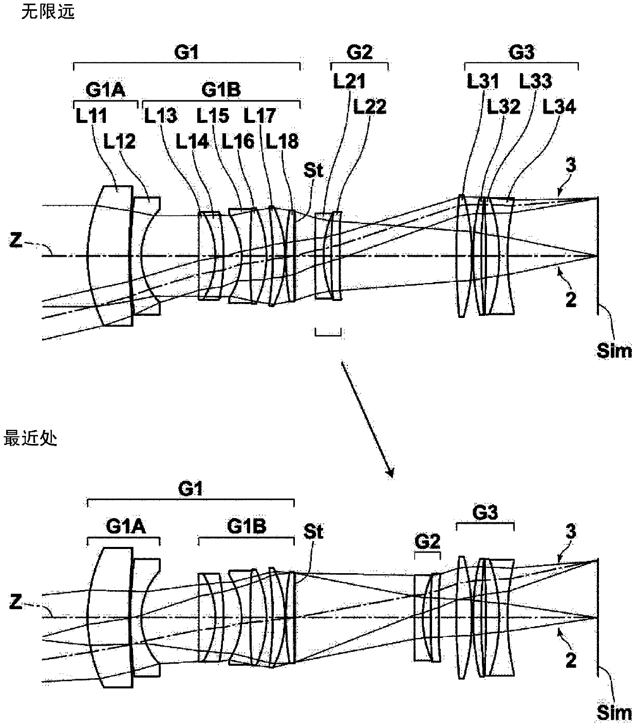
[0228] image 3 The lens structure and optical path of the imaging lens of Example 3 are shown. In the imaging lens of Example 3, the first lens group G1 is composed of a first lens group front group G1A and a first lens group rear group G1B in order from the object side, and the first lens group front group G1A is composed of, in order from the object side, Lenses L11 to L12 are composed of two lenses, the rear group G1B of the first lens group is composed of six lenses L13 to L18 in order from the object side, and the second lens group G2 is composed of two lenses L21 to L22 in order from the object side The third lens group G3 is composed of four lenses, lenses L31 to L34, in order from the object side. Table 7 shows basic lens data of the imaging lens of Example 3, Table 8 shows aspheric coefficients, and Table 9 shows various factors and values of variable surface spacing. Figure 9 Aberration diagrams of the imaging lens of Example 3 are shown.
[0229] 【Table 7】
...
PUM
 Abstract
Description
Claims
Application Information
 - R&D Engineer
- R&D Manager
- IP Professional
- Industry Leading Data Capabilities
- Powerful AI technology
- Patent DNA Extraction
Browse by: Latest US Patents, China's latest patents, Technical Efficacy Thesaurus, Application Domain, Technology Topic, Popular Technical Reports.
© 2024 PatSnap. All rights reserved.Legal|Privacy policy|Modern Slavery Act Transparency Statement|Sitemap|About US| Contact US: help@patsnap.com