
Windshield wiper connecting assembly

A technology for connecting components and wipers, which is applied in vehicle cleaning, vehicle maintenance, transportation and packaging, etc., and can solve problems such as brush bar shaking, large wind resistance, and poor wiping effect

Active Publication Date: 2016-12-21
XIAMEN FUKE CAR ACCESSORIES
View PDF6 Cites 12 Cited by
  • Summary
  • Abstract
  • Description
  • Claims
  • Application Information

AI Technical Summary

Problems solved by technology

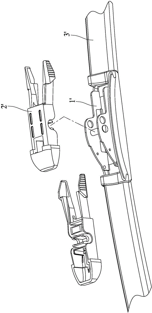
[0002] The connecting assembly used to connect the wiper rod and the wiper arm is generally composed of a connecting seat 1' and a connecting head 2', such as figure 1 As shown, the connecting seat 1' is arranged in the middle of the wiper rod 3', and usually the bottom of the connecting seat 1' is riveted on the wiper rod, and the top surface of the connecting seat 1' is provided with a positioning column or a positioning hole. The connecting head 2' is installed on the connecting seat 1', and is connected with the positioning column or the positioning hole on the connecting seat 1'. The connecting head 2' is provided with a structure matching the wiper arm for connecting with the wiper arm. The overall height of the seat 1' and the connector 2' is relatively high after assembly, generally more than 10mm, so that the wind resistance of the wiper rod 3' is relatively large when it is working, causing the brush rod to vibrate and the wiping effect is poor. In addition, the connecting seat 1' The fit gap between the connector and the connector 2' will also increase the shaking of the wiper rod, so the present invention is an improvement aimed at this deficiency

Method used


Image

  • Windshield wiper connecting assembly
  • Windshield wiper connecting assembly
  • Windshield wiper connecting assembly

Examples


Embodiment Construction

[0019] The present invention will be described in detail below in conjunction with the accompanying drawings and specific implementation.

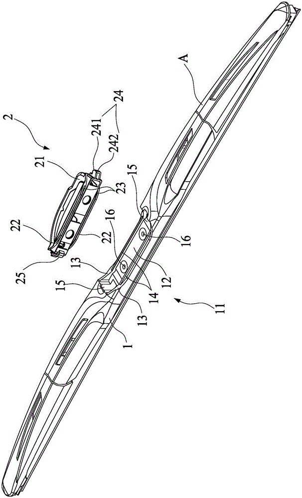
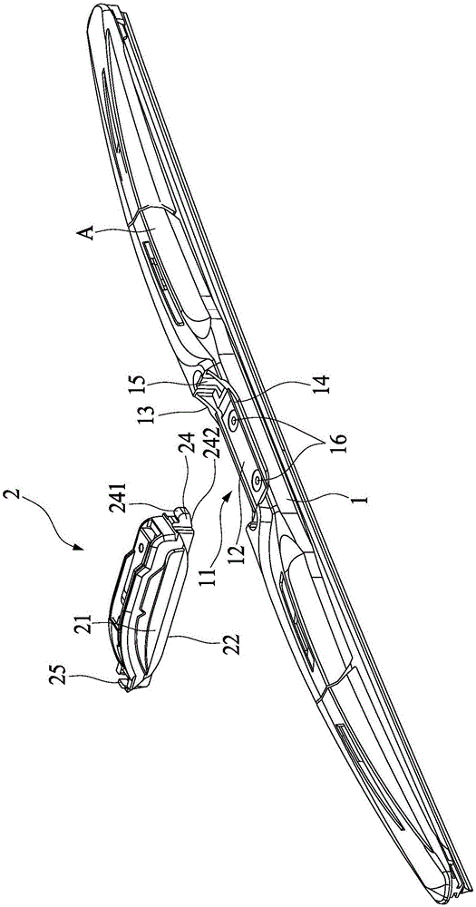
[0020] Such as Figure 2 to Figure 9 As shown, a wiper connection assembly of the present invention includes a connection base 1 and a wiper connector 2. The middle part of the connection base 1 is recessed downward along the length direction to form an open sinker 11. The sinker is boat-shaped and has a horizontal bottom surface 12, And along the two ends of the horizontal bottom surface to the arc surface 13 transitioning to the top of the connecting seat 1, the bottom surface 12 is provided with two parallel and spaced positioning ribs 14 along the length direction, and the middle part of the two arc surfaces 13 of the sinking groove is provided with a positioning groove hole 15;

[0021] The wiper joint 2 is detachably mounted on the sink groove 11 of the connecting seat for connection with the wiper arm (not shown in the figure). The...


PUM


Abstract

The invention discloses a windshield wiper connecting assembly which comprises a connecting seat and a windshield wiper connector. An open sunken groove is formed in the middle of the connecting seat along the length direction of the connecting seat and is provided with a horizontal bottom surface and cambered surfaces, the cambered surfaces extend from two ends of the horizontal bottom surface to the top of the connecting seat in a transition manner, two parallel positioning ribs are arranged on the bottom surface along the length direction of the bottom surface at intervals, and positioning slots are formed in the two cambered surfaces; the windshield wiper connector is detachably mounted on the sunken groove of the connecting seat and is provided with a base, bottom edges are arranged at the bottom of the base, the contour shapes of the bottom edges are matched with the contour shape of the sunken groove of the connecting seat, clamp grooves which are correspondingly matched with the positioning ribs of the sunken groove are formed in the bottom of the base, and clamping structures which are matched with the positioning slots are arranged at two ends of the base.

Description

technical field [0001] The invention relates to the field of vehicle wiper accessories, in particular to a connection assembly for connecting a wiper rod and a wiper arm. Background technique [0002] The connecting assembly used to connect the wiper rod and the wiper arm is generally composed of a connecting seat 1' and a connecting head 2', such as figure 1 As shown, the connecting seat 1' is arranged in the middle of the wiper rod 3', and usually the bottom of the connecting seat 1' is riveted on the wiper rod, and the top surface of the connecting seat 1' is provided with a positioning column or a positioning hole. The connecting head 2' is installed on the connecting seat 1', and is connected with the positioning column or the positioning hole on the connecting seat 1'. The connecting head 2' is provided with a structure matching the wiper arm for connecting with the wiper arm. The overall height of the seat 1' and the connector 2' is relatively high after assembly, ge...

Claims


Application Information

Patent Timeline
IPC IPC(8): B60S1/40
CPCB60S1/4038
Inventor 王书屋
Owner XIAMEN FUKE CAR ACCESSORIES
Learn More