
A worm cam indexing mechanism

A cam indexing and worm technology, which is used in metal processing mechanical parts, precision positioning equipment, metal processing equipment, etc., can solve the problems that the rollers are prone to interference and the motion performance needs to be improved, so as to improve the overall motion performance and smooth motion. , the effect of high speed

Active Publication Date: 2018-08-03
GUANGZHOU HAOZHI ELECTROMECHANICAL
View PDF14 Cites 3 Cited by
  • Summary
  • Abstract
  • Description
  • Claims
  • Application Information

AI Technical Summary

Problems solved by technology

However, this does not improve the motion curve of the worm cam, and the motion performance needs to be improved
At the same time, the rollers are prone to interference when engaging in and out of the groove

Method used


Image

  • A worm cam indexing mechanism
  • A worm cam indexing mechanism
  • A worm cam indexing mechanism

Examples


Embodiment Construction

[0044] Below, in conjunction with accompanying drawing and specific embodiment, the present invention is described further:

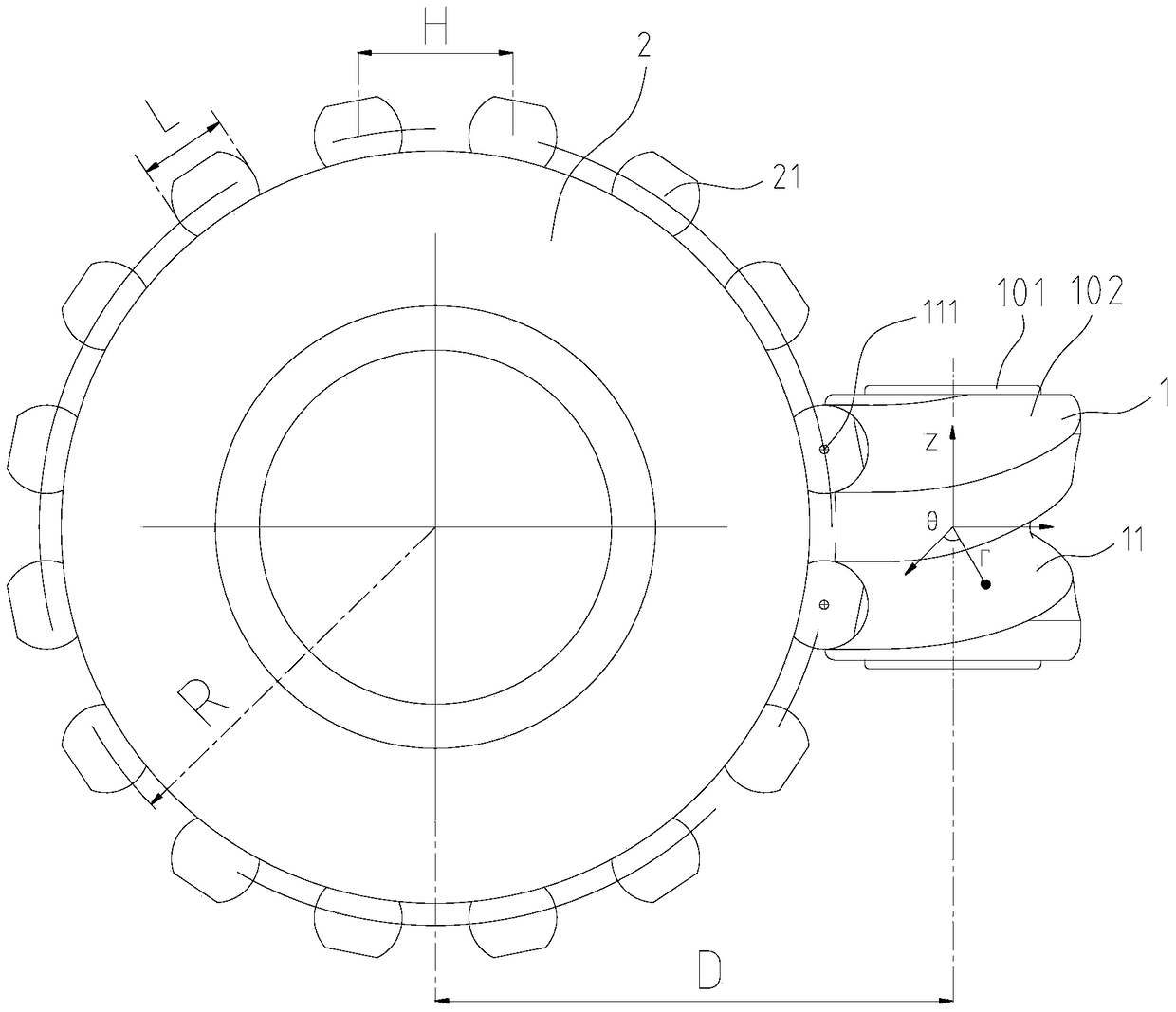
[0045] like Figure 1 to Figure 6 As shown, the worm cam indexing mechanism of the present invention includes a worm cam 1 and a roller disc 2. The worm cam 1 includes a worm 101 and a cam 102 fixed on the worm 101. A channel 11 is opened on the outside of the cam 102. The channel 11 is spiral; the roller disc 2 is provided with a plurality of rollers 21, and the plurality of rollers 21 are distributed along the circumferential direction of the roller disc 2 at intervals, and the rollers 21 are used in the channel 11 sports;

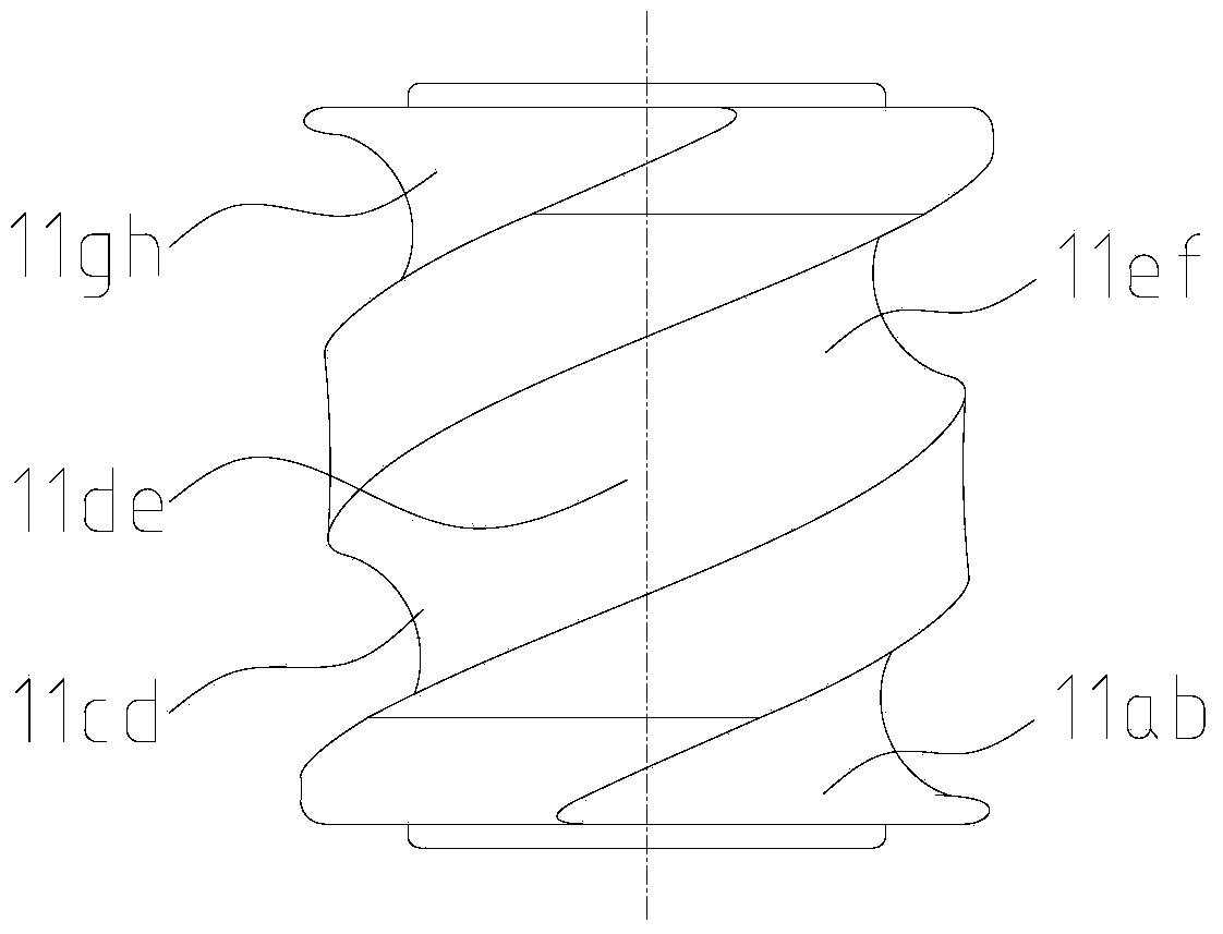
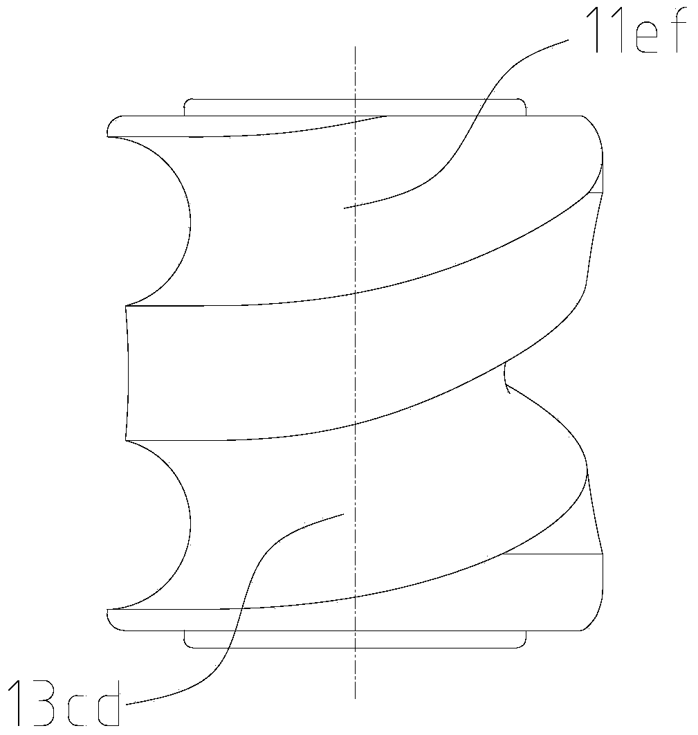
[0046] The channel 11 is sequentially provided with an engaging section 11ab, a first resting section 11bc, a sinusoidal acceleration section 11cd, a constant velocity section 11de, a sinusoidal deceleration section 11ef, a second resting section 11fg, and an engaging section from one end to the other. 11gh, the groove widths of...


PUM


Abstract

A worm cam indexing mechanism, comprising a worm cam and a roller disc, the worm cam comprises a worm and a cam fixed on the worm, a channel is opened on the outside of the cam, and the channel is helical; the roller disc is A plurality of rollers are provided, and the plurality of rollers are distributed at intervals along the circumference of the roller disc. The rollers are used to move in the groove, and the groove is provided with an engaging section, a first stop Segment, sinusoidal acceleration segment, constant velocity segment, sinusoidal deceleration segment, second rest segment and engagement segment. The invention can improve the overall movement performance of the mechanism, and avoid the interference of the rollers when engaging in and out of the groove.

Description

technical field [0001] The invention relates to an indexing device, in particular to a worm cam indexing mechanism. Background technique [0002] The commonly used worm cam indexing mechanism mainly includes: a worm cam, a roller disc, and rollers, and the rollers are arranged at equal intervals on the radial circumference of the roller disc. A groove is arranged on the worm cam, and the groove can be divided into a rest groove and a motion groove. When working, there are two rollers that are always engaged with the groove. When the worm cam is driven to rotate in situ, if the roller engages in the rest channel, the roller disc remains stationary; if the roller engages in the moving channel, the roller disc produces a rotary motion under the engagement of the channel; thus The intermittent motion (rotation) of the roller disc can be realized. [0003] Because the effect of intermittent motion (rotation) is good, the above-mentioned worm cam indexing mechanism is widely us...

Claims


Application Information

Patent Timeline
Patent Type & Authority Patents(China)
IPC IPC(8): B23Q16/02
CPCB23Q16/022
Inventor 雷群庄剑毅
Owner GUANGZHOU HAOZHI ELECTROMECHANICAL
Learn More