
Jump rope grip assembly having adjustable weight and number counting function

a technology of number counting and jump rope, which is applied in the field of jump rope grip assembly, can solve the problems of limiting the exercise effect and and achieve the effect of enhancing the exercise effect of the jump rope and enhancing the versatility of the jump rop

Inactive Publication Date: 2011-07-12
HSU CHI KUN
View PDF4 Cites 27 Cited by
  • Summary
  • Abstract
  • Description
  • Claims
  • Application Information

AI Technical Summary

Benefits of technology

[0010]According to the primary advantage of the present invention, the counter can count and indicate the jump number of the jump rope so that the user can know the jump number exactly and can precisely evaluate the calories of consumption during the jumping process so as to enhance the exercising effect of the jump rope.
[0011]According to another advantage of the present invention, the weight member provides a damping force to the user' arms so as to exercise the user's arms, thereby enhancing the versatility of the jump rope.
[0012]According to a further advantage of the present invention, the weight of the weight member can be adjusted by the counterbalances so as to fit the requirements of different users.
[0013]Further benefits and advantages of the present invention will become apparent after a careful reading of the detailed description with appropriate reference to the accompanying drawings.BRIEF DESCRIPTION OF THE SEVERAL VIEWS OF THE DRAWING(S)
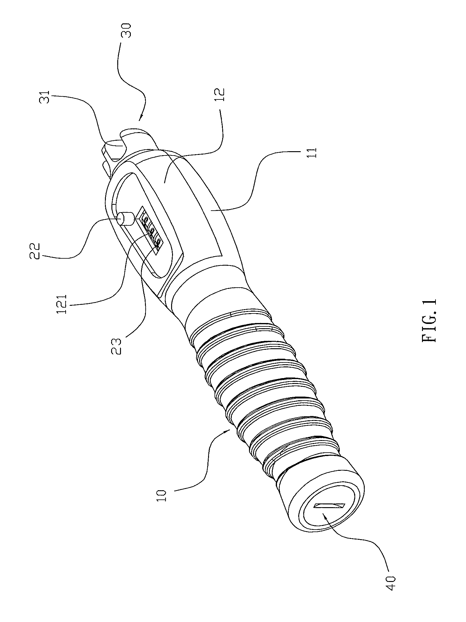
[0014]FIG. 1 is a perspective view of a grip assembly for a jump rope in accordance with the preferred embodiment of the present invention.
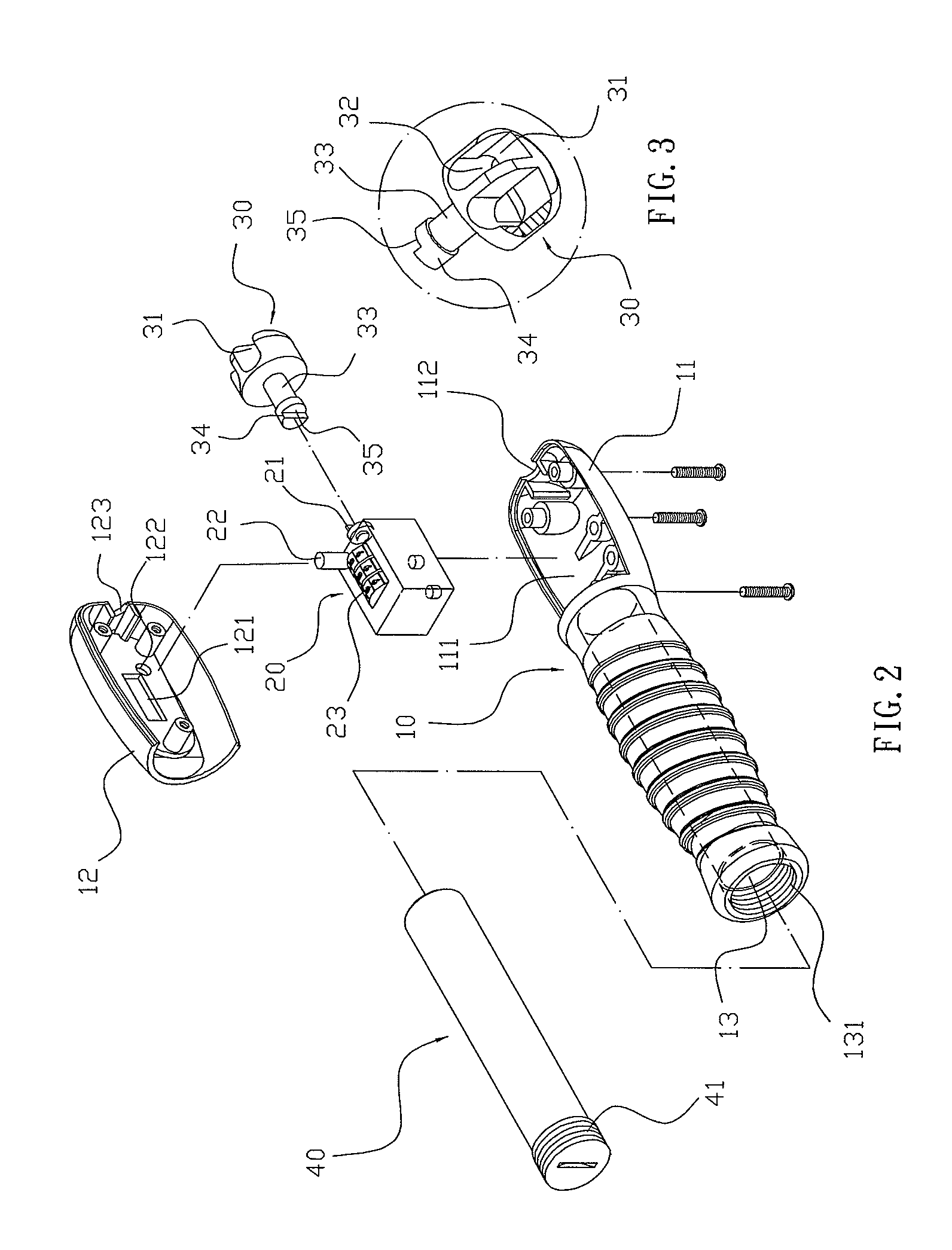
[0015]FIG. 2 is an exploded perspective view of the grip assembly for a jump rope as shown in FIG. 1.

Problems solved by technology

However, the user doesn't know the jump number exactly, so that he / she cannot precisely evaluate the calories of consumption during the jumping process, thereby limiting the exercising effect of the jump rope.
In addition, the conventional jump rope only has a single function, thereby limiting the versatility of the jump rope.

Method used


Image

  • Jump rope grip assembly having adjustable weight and number counting function
  • Jump rope grip assembly having adjustable weight and number counting function
  • Jump rope grip assembly having adjustable weight and number counting function

Examples


Embodiment Construction

[0024]Referring to the drawings and initially to FIGS. 1-6, a grip assembly for a jump rope in accordance with the preferred embodiment of the present invention comprises a grip body 10 having a first end formed with an open casing 11 and a second end formed with a receiving space 13, a counter 20 mounted in the casing 11 of the grip body 10, a cover 12 mounted on the casing 11 of the grip body 10 and abutting the counter 20 to locate the counter 20 between the casing 11 of the grip body 10 and the cover 12, a pivot head 30 rotatably mounted on the casing 11 of the grip body 10 and connected with the counter 20 to drive the counter 20, and a weight member 40 mounted in the receiving space 13 of the grip body 10.

[0025]The casing 11 of the grip body 10 has an inner portion formed with a receiving recess 111 to receive the counter 20. The casing 11 of the grip body 10 has an end face formed with a passage 112 connected to the receiving recess 111. The receiving space 13 of the grip bod...


PUM


Abstract

A grip assembly for a jump rope includes a grip body having a first end formed with an open casing and a second end formed with a receiving space, a counter mounted in the casing, a cover mounted on the casing and abutting the counter to locate the counter between the casing and the cover, a pivot head rotatably mounted on the casing and connected with the counter to drive the counter, and a weight member mounted in the receiving space of the grip body. Thus, the counter can count and indicate the jump number of the jump rope so that the user can know the jump number exactly. In addition, the weight member provides a damping force to the user' arms so as to exercise the user's arms.

Description

BACKGROUND OF THE INVENTION[0001]1. Field of the Invention[0002]The present invention relates to a grip assembly and, more particularly, to a grip assembly for a jump rope.[0003]2. Description of the Related Art[0004]A conventional jump rope comprises a rope and two grips mounted on two opposite ends of the rope. Thus, a user's two hands can hold the two grips to revolve the rope in circles so as to achieve an exercising effect. However, the user doesn't know the jump number exactly, so that he / she cannot precisely evaluate the calories of consumption during the jumping process, thereby limiting the exercising effect of the jump rope. In addition, the conventional jump rope only has a single function, thereby limiting the versatility of the jump rope.BRIEF SUMMARY OF THE INVENTION[0005]In accordance with the present invention, there is provided a grip assembly for a jump rope, comprising a grip body having a first end formed with an open casing and a second end formed with a receivi...

Claims


Application Information

Patent Timeline
Patent Type & Authority Patents(United States)
IPC IPC(8): A63B21/00
CPCA63B5/20A63B21/072A63B2220/17
Inventor HSU, CHI-KUN
Owner HSU CHI KUN
Learn More