


Quick Research
Generate reliable direction feasibility study reports for your R&D in just a few steps.

Technical Q&A
Discover and master advanced knowledge NOW. Basics, ideas, possibilities, all at once.

Find Solutions
As an expert in R&D theories, this can generate solutions to your technical problems instantly.

Evaluate Feasibility
Analyze your overall solution with one click, know your potential R&D risks in advance.

Monitor Landscape
Get weekly tech updates, stay abreast of the latest tech innovations and key insights.
Pipe type foot-controlled climbing device
A climbing device and foot control technology, applied in the field of climbing, can solve problems such as poor safety and reliability, and achieve the effects of safe and reliable locking, broad market prospects, and beautiful appearance
- Summary
- Abstract
- Description
- Claims
- Application Information
AI Technical Summary
Problems solved by technology
Method used
Image

Examples
Embodiment 1
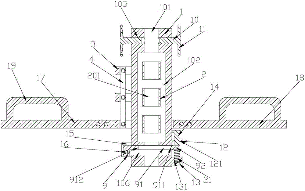
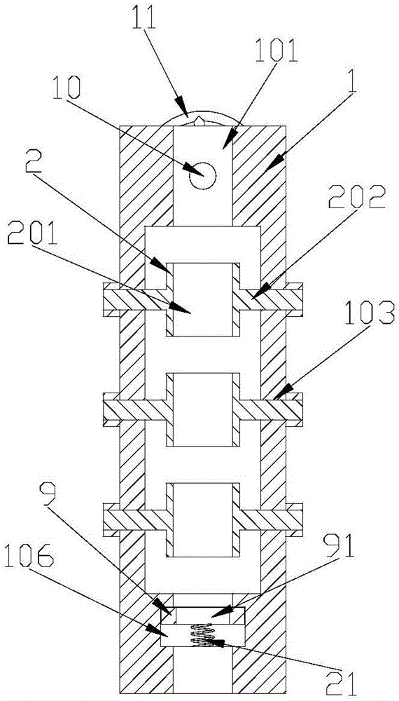
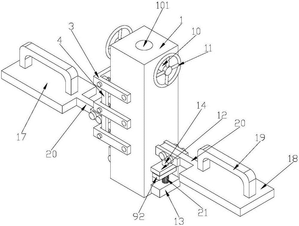
[0041] Such as Figure 1 to Figure 3 As shown, the rotating device includes three first U-shaped frames 3 with openings facing the rope tube main body 1, and the number of locking sleeves 2 is three, and the locking sleeves 2 are evenly distributed in the rotating space 102. The first U-shaped frames 3 The ends of the two sidewalls are fixedly connected to the ends of the locking sleeve rotating shaft 202 passing through the side wall of the rope tube main body 1, respectively, and the first U-shaped frame 3 is perpendicular to the axis of the locking sleeve 2 respectively. The first U-shaped frame 3 limits the locking sleeve 2 and keeps the locking sleeve 2 directly below the guide rope hole 101 . On the two side walls of the first U-shaped frame 3, one side near the middle part of the first U-shaped frame 3 is respectively hinged with the side walls of two transmission linkages 4 vertically arranged, and the transmission linkage 4 connects the three The first U-shaped frame...
Embodiment 2
[0043] Such as Figure 4 to Figure 6 As shown, the rotary device includes four transmission gears 5 and two intermediate gears 7 . The number of locking sleeves 2 is two, and the locking sleeves 2 are evenly distributed in the rotating space 102 , and the rotating shafts 202 of the locking sleeves passing through the side wall of the rope tube main body 1 are respectively fixedly connected with the transmission gear 5 . The lower two locking sleeve rotating shafts 202 are also respectively affixed to the free ends of the two side walls of the second U-shaped frame 6, the second U-shaped frame 6 is perpendicular to the axis of the locking sleeve 2, and the moving pedal 17 is close to One end of the rope tube main body 1 is fixedly connected to the middle part of the second U-shaped frame 6 . Transmission between transmission gear 5 and transmission gear 5 is carried out by transition gear 7, and transition gear 7 is rotatably arranged on the positioning shaft 8 fixed on the ou...
PUM
 Abstract
Description
Claims
Application Information
 - R&D Engineer
- R&D Manager
- IP Professional
- Industry Leading Data Capabilities
- Powerful AI technology
- Patent DNA Extraction
Browse by: Latest US Patents, China's latest patents, Technical Efficacy Thesaurus, Application Domain, Technology Topic, Popular Technical Reports.
© 2024 PatSnap. All rights reserved.Legal|Privacy policy|Modern Slavery Act Transparency Statement|Sitemap|About US| Contact US: help@patsnap.com