Stator of an electric machine and production thereof

A technology for stators and rotating electrical machines, applied in the manufacture of motor generators, use/manufacture of slot locking devices, electromechanical devices, etc., can solve problems such as laborious, manual insulation, and time-consuming

Active Publication Date: 2016-12-14
SIEMENS AG
View PDF5 Cites 15 Cited by
  • Summary
  • Abstract
  • Description
  • Claims
  • Application Information

AI Technical Summary

Problems solved by technology

Manufacturing such coil geometries is cumbersome and time consuming
Especially narrow radius areas in the area of ​​the winding heads often have to be insulated manually, since the winding machines for such areas have to be considerably longer in use and set up with greater effort

Method used


Image

  • Stator of an electric machine and production thereof
  • Stator of an electric machine and production thereof
  • Stator of an electric machine and production thereof

Examples


Embodiment Construction

[0057] Mutually equivalent parts are provided with the same reference symbols in all figures.

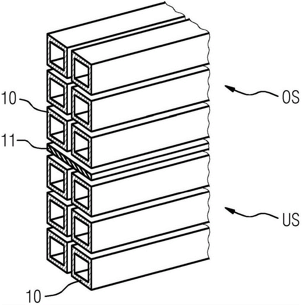
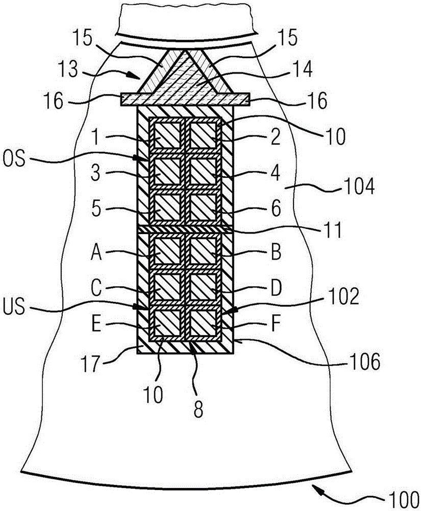
[0058] Figures 1 to 6 A first exemplary embodiment of a stator 100 of a rotating electrical machine and a method for the automated production of a winding 102 of the stator 100 are shown. The stator 100 has a lamination stack 104 with a plurality of grooves 106 opening towards the air gap between the rotor of the electric machine and the stator 100 . The winding 102 consists of coils, the turns of which each run through the grooves 106 of the laminated core 104 .

[0059] To manufacture the winding 102, in a variant of this embodiment first a plurality of figure 1 The straight, pipe-shaped insulating hollow body 10 shown in , is made of an electrically insulating insulating material, preferably a ceramic material. Each insulating hollow body 10 has at least the length of the groove 106 and has a cross-section with a triangular outer profile. The insulating hollow bodies 10 are...


PUM


Abstract

The invention relates to a stator (100) of a rotating electric machine, the stator (100) comprising: a laminate stack (104) having a plurality of slots (106) open towards an air gap between the stator (100) and a rotor of the electric machine; and a winding (102) having a plurality of coils, the turns of said winding each passing through slots (106) of the laminate stack (104). In this case, the turns of the coils within the slots (106) are electrically insulated from one another and from the laminate stack (104) by a ceramic material. In addition, the invention relates to a method for the automated production of a winding (102) of a stator (100) of a rotating electric machine.

Description

technical field [0001] The invention relates to a stator of a rotating electric machine and a method for the automated production of a winding of a stator of a rotating electric machine. Background technique [0002] Rotating electric machines, in particular high-voltage asynchronous machines, usually consist of a laminated core with punched grooves and a so-called distributed winding inserted therein. The winding consists of individual coils which have a relatively complex three-dimensional geometry. Manufacturing such coil geometries is cumbersome and time-consuming. In particular, narrow-radius areas in the area of ​​the winding heads often have to be insulated manually, since the winding machines for such areas have to be considerably longer in use and require more effort to set up. This is necessary due to the high degree of variability required for specific customer solutions. This leads to the fact that usually only one coil arrangement of the same construction typ...

Claims


Application Information

Patent Timeline
Patent Type & Authority Applications(China)
IPC IPC(8): H02K1/16H02K3/34H02K15/085
CPCH02K1/16H02K3/345H02K15/085H02K3/14H02K3/30H02K3/34H02K3/38H02K3/493H02K15/0081H02K15/0414H02K15/105H02K1/04H02K1/146H02K3/12H02K3/18H02K15/0018H02K15/022H02K15/062
Inventor 马蒂亚斯·舍雷尔克里斯蒂安·德格本亚明·艾兴格埃里克·约瑟夫乌韦·沙夫迈克尔·施特格赫尔塞巴斯蒂安·魏斯
Owner SIEMENS AG
Why Eureka
Try Eureka