
Smart solenoid

An electromagnetic and coil technology, applied in electromagnets, electromagnets with armatures, magnets, etc., can solve problems such as increasing the complexity of system wiring

Active Publication Date: 2016-12-14
FLEXTRONICS AP LLC
View PDF8 Cites 4 Cited by
  • Summary
  • Abstract
  • Description
  • Claims
  • Application Information

AI Technical Summary

Problems solved by technology

This approach increases system wiring complexity and requires the ECU to be designed to control the fluid control valve

Method used


Image

  • Smart solenoid
  • Smart solenoid
  • Smart solenoid

Examples


Embodiment Construction

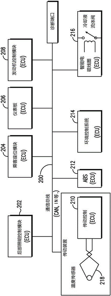
[0014] Controller Area Network (CAN) is a high-speed communication bus that carries messages between Electronic Control Units (ECUs) in an automobile. ECUs typically send signals to the devices they control via a local interconnect network (LIN). LIN is a low-cost, low-speed communication bus commonly used between an ECU and the device it monitors or controls.

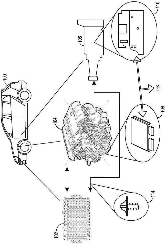
[0015] figure 1 An automobile 100 is shown having a radiator 102 , an engine 104 , and a transmission 106 . An engine control unit 108 may electronically control devices in the engine 104 and a transmission control unit (TCU) 110 may electronically control devices in the transmission 106 . Engine control unit 108 , TCU 110 and other vehicle systems may be connected to wiring harness 112 . In an embodiment of the invention, the automobile 100 has a coolant line running between the radiator 102 and the transmission 106, which can be used to regulate the temperature of the transmission. The TCU 110 may monitor the tem...


PUM


Abstract

A solenoid fluid control valve is disclosed for controlling fluid flow. The solenoid fluid control valve may comprise a transceiver that receives a signal via a controller area network (CAN) bus, and a micro controller unit that decodes the signal to determine a temperature. The micro controller unit may send a signal to a driver circuit based on the temperature. The driver circuit may send a current through a coil in response to the signal, wherein an armature moves in response to the current through the coil. The movement of the armature may direct a cooling fluid flow.

Description

[0001] Cross References to Related Applications [0002] This application claims the benefit of US Nonprovisional Application Serial No. 14 / 222,132 filed March 21, 2014, the contents of which are hereby incorporated by reference. technical field [0003] The present invention relates to an electromagnetic fluid control valve for regulating the temperature of transmission fluid. Background technique [0004] Fluid control valves may be used to regulate the temperature of automotive equipment such as the engine or transmission. Above a certain threshold, the lubricating oil in the equipment can start to burn, reducing the efficiency of the equipment. Fluid control valves can be used to direct equipment-specific coolant through the radiator, thereby reducing the temperature of the equipment. [0005] The fluid control valve may be a mechanical valve that does not require electrical control signaling. Alternatively, the fluid control valve may be controlled by an electronic c...

Claims


Application Information

Patent Timeline
IPC IPC(8): F16K31/06H01F7/18F01P7/16F01P11/14
CPCF01P7/167F01P11/14F01P2007/146F01P2031/00H01F2007/185G05D23/19H01F7/1844F16H57/0412F16K31/0644F16K31/0675F16K31/082F16K37/0041F16K37/0083
Inventor D·菲利普斯R·古索雷克
Owner FLEXTRONICS AP LLC
Learn More