
Radio interference source locating method

A radio interference and source location technology, applied in the field of communication, can solve problems such as low efficiency and complicated positioning methods

Active Publication Date: 2016-12-14
汪瑞
View PDF3 Cites 3 Cited by
  • Summary
  • Abstract
  • Description
  • Claims
  • Application Information

AI Technical Summary

Problems solved by technology

[0004] The purpose of the present invention is to overcome the shortcomings of the traditional radio interference source location method being complex and inefficient, and to provide a radio interference source location method that can quickly calculate the location of the radio interference source through one monitoring

Method used


Image

  • Radio interference source locating method
  • Radio interference source locating method
  • Radio interference source locating method

Examples


Embodiment Construction

[0047] The present invention will be described in further detail below in conjunction with the accompanying drawings.

[0048] The first step is to calculate the propagation distance

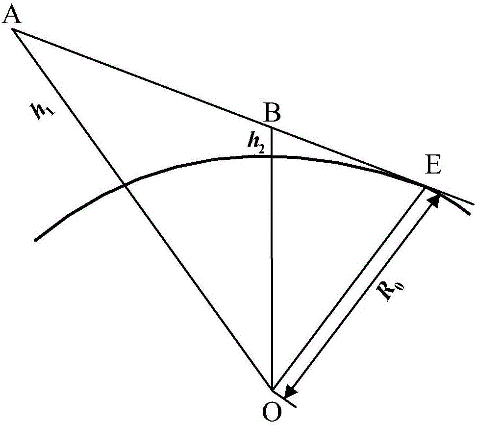
[0049] Since the earth is spherical, when the height of the transmitting and receiving antenna on the ground is determined, there is a corresponding maximum distance that can be reached by the line of sight, such as figure 1 shown. Let the heights of transmitting antenna A and receiving antenna B be h 1 and h 2 , connecting AB, its extension line is tangent to the earth's surface at point E, then AE is the farthest distance that the direct wave can reach.

[0050] Let the radius of the earth be R 0 , the antenna heights are h 1 and h 2 , then in the right triangle AEO,

[0051] A E = AO 2 ...


PUM


Abstract

Provided is a radio interference source locating method. In view of the problem that the traditional radio interference source locating method is complex and of low efficiency, a radio interference source locating principle based on a handheld monitoring receiver is researched. The invention proposes a novel single-point radio interference source locating method, which can be used to calculate out the position of a radio interference source quickly through one monitoring. Field measurement results show that the method is an effective and quick radio interference source locating method.

Description

technical field [0001] The invention belongs to a positioning method in the communication field, and in particular relates to a radio interference source positioning method. Background technique [0002] Radio interference location uses direction-finding equipment to determine the direction of electromagnetic waves, thereby determining the location of the source of the radio signal emission. It is a comprehensive subject that widely combines radar principles, radar signal processing, communication principles, computer technology, digital signal processing and other disciplines. In the military field, reconnaissance and positioning of radio equipment equipped with military facilities such as ports, airports, warships, and missile launch sites, and the implementation of targeted electronic interference and military strikes have important applications; in the civilian field, it can be used in traffic control, life rescue, Aspects such as radio spectrum management play an impor...

Claims


Application Information

Patent Timeline
IPC IPC(8): H04B17/27H04B17/10G01S5/06
CPCG01S5/06H04B17/102H04B17/27
Inventor 汪瑞
Owner 汪瑞
Learn More