
Method for measuring magnetic field by aid of superconducting quantum interference device and positioning current source of magnetic field

A technology of superconducting quantum interference and magnetic field current, applied in diagnostic recording/measurement, applications, sensors, etc., can solve the problems of complex hardware system and increased equipment cost, and achieve the effect of simple positioning method and hardware cost saving

Inactive Publication Date: 2013-10-16
TONGJI UNIV
View PDF3 Cites 0 Cited by
  • Summary
  • Abstract
  • Description
  • Claims
  • Application Information

AI Technical Summary

Problems solved by technology

In order to improve the accuracy of source location, the number of channels for measuring the magnetic field with SQUID is increasing, which also leads to an increase in equipment cost
A general commercial cardiac magnetic field measurement system needs to use 36-64 channel SQUIDs arranged in 6X 6 to measure the magnetic field signal synchronously. Not only the hardware system is complex, but also the calculation method and calculation software for the inverse problem of magnetic field source location also face many problems.

Method used


Image

  • Method for measuring magnetic field by aid of superconducting quantum interference device and positioning current source of magnetic field
  • Method for measuring magnetic field by aid of superconducting quantum interference device and positioning current source of magnetic field
  • Method for measuring magnetic field by aid of superconducting quantum interference device and positioning current source of magnetic field

Examples


Embodiment

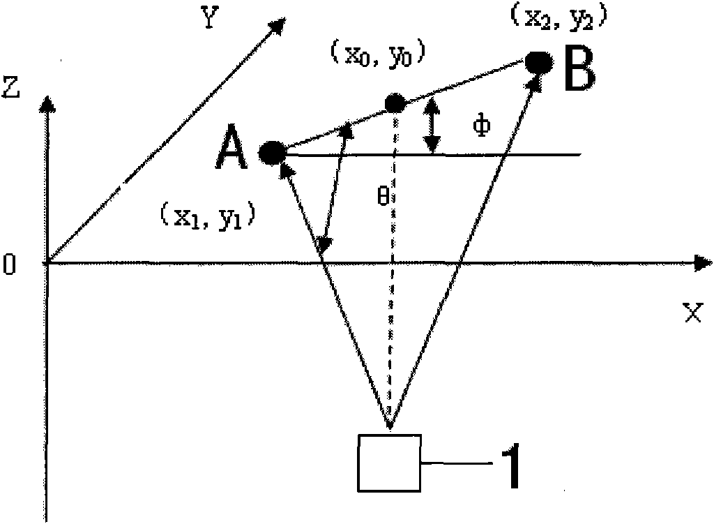
[0030] figure 1 There are two measurement points A and B in a given coordinate system. Point A represents the position of the maximum value of the magnetic field, and point B represents the position of the minimum value of the magnetic field. Below the measurement plane composed of X-Y coordinates, there is a current dipole source that generates the measured magnetic field at a depth d. The angle between the line connecting the measuring point A and the current dipole on the measuring plane is θ, and the angle between the line connecting measuring points A and B on the measuring plane and the X axis is

[0031] When using this method to locate the source of the measured magnetic field, the basic principles are as follows: figure 1 shown.

[0032] Under the quasi-static approximation of the Maxwell equation, according to the Biot-Savart law, the magnetic induction generated by a current dipole in space is:

[0033] B z ...


PUM


Abstract

The invention relates to a method for measuring a magnetic field by the aid of a superconducting quantum interference device and positioning a current source of the magnetic field. The method comprises following steps: 1) acquiring magnetic field signals on a small quantity of measuring points by the aid of the superconducting quantum interference device; 2) obtaining a magnetic field maximum value and a magnetic field minimum value at every moment according to the measured magnetic field signals; and 3) obtaining position and strength parameters of a magnetic field source after a computer processes the magnetic field maximum value and the magnetic field minimum value at every moment in the step 2). Compared with the prior art, the method has the advantages of simplicity, effectiveness, capability of greatly saving cost of hardware, and the like.

Description

technical field [0001] The invention relates to a method for locating a magnetic field current source, in particular to a method for measuring a magnetic field and locating a magnetic field current source with a superconducting quantum interference device. Background technique [0002] From 1970 to 1976, D. Cohen et al. proposed for the first time the method of measuring the magnetic field signal of the heart with a superconducting quantum interference device (SQUID) in the laboratory and locating an equivalent current dipole source. In the past 40 years, the research on magnetic field detection and source location has attracted great attention from various countries. The scope of application continues to expand. In order to improve the accuracy of source location, the number of channels for measuring the magnetic field with SQUID is increasing, which also leads to an increase in equipment cost. A general commercial cardiac magnetic field measurement system needs to use 36...

Claims


Application Information

Patent Timeline
Patent Type & Authority Patents(China)
IPC IPC(8): A61B5/05
Inventor 蒋式勤石明伟朱俊杰
Owner TONGJI UNIV
Learn More