
Pumping unit wellhead packing box

A technology for pumping wells and packing boxes, which is applied in wellbore/well parts, earthwork drilling, sealing/isolation, etc. It can solve the problems of shortening the service life of packing, reducing oil production efficiency, and increasing production costs, and achieves The effect of avoiding oil spill accidents, reducing accident damage and prolonging service life

Active Publication Date: 2018-08-14
JINGZHOU GAOXIN PETROLEUM VALVE MEMBER
View PDF8 Cites 0 Cited by
  • Summary
  • Abstract
  • Description
  • Claims
  • Application Information

AI Technical Summary

Problems solved by technology

[0003] During the installation of the packing box, the polished rod of the pumping unit and the wellhead device are prone to offset, that is, the center line of the polished rod and the wellhead deviates. The conventional packing box does not have the ability to adjust the eccentricity of the pumping unit polished rod and the wellhead device, resulting in During the oiling process, eccentric wear occurs between the oil pumping polished rod and the packing box. As the pumping unit drives the polished rod to move up and down repeatedly, eccentric wear occurs between the polished rod and the packing box, causing the packing of the packing box to wear out quickly. oil spill
At this time, it is necessary to shut down the pumping unit, disassemble the packing box, and replace the new packing, which requires frequent replacement of the packing, shortens the service life of the packing, causes short-term shutdown of the oil well, increases the number of operations and the time of shutting down the well, and thus Resulting in lower oil recovery efficiency and increased production costs

Method used


Image

  • Pumping unit wellhead packing box

Examples


Embodiment Construction

[0030] The present invention will be described in further detail below in conjunction with the accompanying drawings and embodiments, so that those skilled in the art can implement it with reference to the description.

[0031] It should be understood that terms such as "having", "comprising" and "including" as used herein do not entail the presence or addition of one or more other elements or combinations thereof.

[0032] It should be noted that the experimental methods described in the following embodiments, unless otherwise specified, are conventional methods, and the reagents and materials, unless otherwise specified, can be obtained from commercial sources.

[0033] In the description of the present invention, the terms "transverse", "longitudinal", "upper", "lower", "front", "rear", "left", "right", "vertical", "horizontal", " The orientations or positional relationships indicated by "top", "bottom", "inner", "outer", etc. are based on the orientations or positional rel...


PUM


Abstract

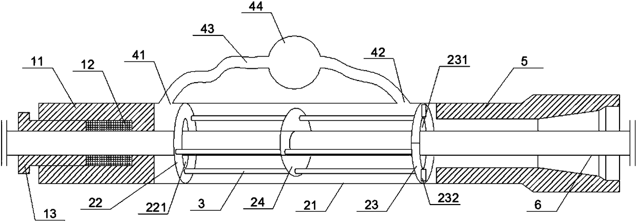
The invention discloses a wellhead packing box of a pumping unit. The wellhead packing box comprises a sealing mechanism, a deviation adjustment mechanism and a buffer mechanism, wherein the deviation adjustment mechanism comprises a first round disk, a second round disk, a ring disposed between the first round disk and the second round disk, and four connecting rods used to connect the first round disk, the ring and the second round disk. The deviation adjustment mechanism is disposed between the packing box and an oil extraction connector, so that a polish rod and the packing box can be installed at an oil extraction hole concentrically, and deviation of the polish rod from the packing box can be avoided. During oil extraction, the polish rod can only be moved up and down in the vertically direction under cooperation effects of the first round disk, the second round disk and the ring, and deviation from the packing box will not take place, so that eccentric wear of the polish rod to packing can be avoided, and a service life of the packing box can be prolonged. Meanwhile, the buffer mechanism is designed, so that oil overflowed from a wellhead to inside of a shell body can flow circularly, and the problem that the excessive overflowed oil flows upwards to pollute the packing box or even leaks out from the upper part of the packing box can be avoided.

Description

technical field [0001] The invention relates to the technical field of auxiliary equipment for oil field pumping units. More specifically, the present invention relates to a wellhead packing box of a pumping unit. Background technique [0002] The packing box is the sealing device of the polished rod at the wellhead of the pumping unit. It is an important part to prevent oil spillage. The packing box is set on the outside of the polished rod of the pumping unit. For the function of sealing, the lower end of the packing box is fixed on the wellhead device. During the oil pumping operation, the polished rod of the pumping unit moves up and down repeatedly relative to the packing box. [0003] During the installation of the packing box, the polished rod of the pumping unit and the wellhead device are prone to offset, that is, the center line of the polished rod and the wellhead deviates. The conventional packing box does not have the ability to adjust the eccentricity of the p...

Claims


Application Information

Patent Timeline
Patent Type & Authority Patents(China)
IPC IPC(8): E21B33/03
CPCE21B33/03
Inventor 高忠平李高翔高舒雅董小庆
Owner JINGZHOU GAOXIN PETROLEUM VALVE MEMBER
Learn More