
Tool for adjusting wrist clearances of industrial robot

A technology for industrial robots and debugging tooling, applied in the direction of manipulators, manufacturing tools, etc., can solve problems such as trouble, increased wrist gap, and complexity, and achieve the effect of reducing manufacturing costs

Inactive Publication Date: 2016-12-14
ANHUI LEADING PRECISION TECH
View PDF5 Cites 2 Cited by
  • Summary
  • Abstract
  • Description
  • Claims
  • Application Information

AI Technical Summary

Problems solved by technology

At present, after the existing industrial robots (especially offset robots) are assembled in the assembly workshop, there are usually gaps in the three axes of the wrist, that is, the gear assembly in the 4th, 5th, and 6th axes, but this gap is in the industry. The robot cannot be felt by hand after it has just been assembled. It will only appear after high-speed movement and running-in after it has actually worked continuously for several hours. For this reason, the routine practice of debugging workers is: first let the assembled industrial robot work normally , after there is a gap in the three axes of the wrist, remove the wrist from the industrial robot, then use the adjusting gasket to adjust the gap, and then reinstall it on the industrial robot after adjustment, and then run and debug. After a period of After a period of time, the wrist gap will become larger again, and it will be disassembled from the industrial robot again to adjust the gap. Obviously, this gap adjustment method needs to repeatedly disassemble the wrist from the industrial robot. The whole process is not only complicated and cumbersome, but also will increase the production cost of the enterprise

Method used


Image

  • Tool for adjusting wrist clearances of industrial robot
  • Tool for adjusting wrist clearances of industrial robot

Examples


Embodiment Construction

[0014] The following is a further detailed description of the industrial robot wrist gap debugging tool of the present invention in conjunction with the accompanying drawings and specific embodiments:

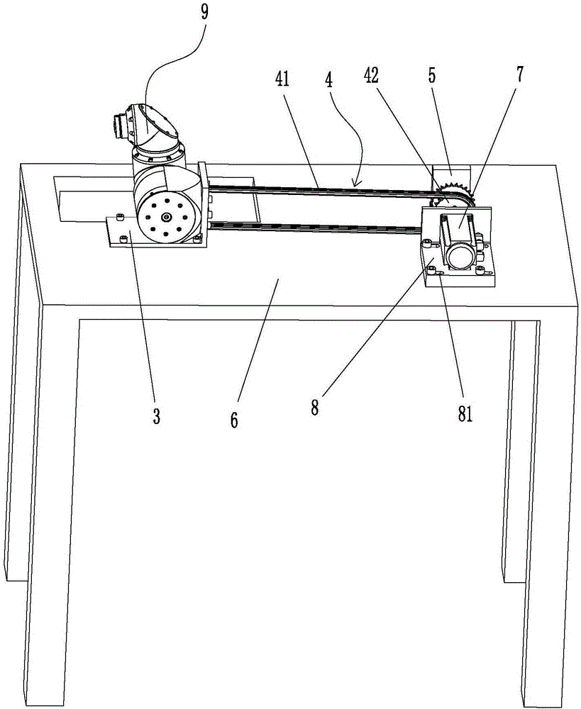
[0015] Such as figure 1 As shown, in this specific embodiment, the industrial robot wrist gap debugging tool of the present invention includes a workbench 6, a wrist fixing plate 3, a motor 7, and a drive mechanism 4 for driving the rotation of three axes on the wrist. The drive mechanism 4 and Motor 7 is connected, and wrist fixed plate 3 and motor 7 are all installed on the workbench 6. Described drive mechanism 4 comprises chain 41 and sprocket wheel 42, and sprocket wheel 42 is contained on the motor 7 rotating shafts, and chain 41 right-hand ends engage with sprocket wheel 42, and after chain 41 left-hand ends pass through the through hole that offers on wrist fixing plate 3, respectively Used to mesh with the sprockets on the three axes of the wrist.

[0016] As prefera...


PUM


Abstract

A tool for adjusting the wrist clearances of an industrial robot comprises a working table, a wrist fixing plate, a motor and a driving mechanism used for driving three shafts on a wrist to rotate, wherein the driving mechanism is connected with the motor, the wrist fixing plate and the motor are both mounted on the working table, the driving mechanism comprises a chain and a chain wheel, the chain wheel is mounted on a rotating shaft of the motor, one end of the chain is meshed with the chain wheel, and the other end of the chain, after penetrating through a through hole formed in the wrist fixing plate, is meshed with a chain wheel on the three shafts of the wrist. Before the wrist is assembled on the industrial robot, first, the wrist is mounted on the wrist fixing plate, then, the three shafts in the wrist are separately driven by the driving mechanism to continuously work for 120 hours, the clearances of the three shafts are fully displayed, and after no clearances exist after adjustment, the wrist is mounted on the industrial robot at a time. In conclusion, a following wrist disassembling and assembling procedure is omitted in a mode of previously adjusting the clearances of the wrist, so that the production cost of enterprises is greatly saved.

Description

technical field [0001] The invention relates to a gap debugging device for an industrial robot, in particular to a wrist gap debugging tool for an industrial robot with an offset wrist. Background technique [0002] We know that most of the functions of industrial robots are completed by the mechanical arm, and the wrist is an important part connected to the mechanical arm. The reliability of its operation will directly affect the quality and precision of the industrial robot. At present, after the existing industrial robots (especially offset robots) are assembled in the assembly workshop, there are usually gaps in the three axes of the wrist, that is, the gear assembly in the 4th, 5th, and 6th axes, but this gap is in the industry. The robot cannot be felt by hand after it has just been assembled. It will only appear after high-speed movement and running-in after it has actually worked continuously for several hours. For this reason, the routine practice of debugging worke...

Claims


Application Information

Patent Timeline
IPC IPC(8): B25J19/00
CPCB25J19/0066
Inventor 胡建设戚红岩陈兰郜春海王寅光冷静
Owner ANHUI LEADING PRECISION TECH
Learn More