
Shell, shell manufacturing method and electronic device

A technology for electronic devices and shells, which is applied in the direction of metal shells, etc., can solve the problems of insufficient connection and insufficient overall strength of the shell, and achieve the effect of enhancing the overall strength

Active Publication Date: 2016-12-07
GUANGDONG OPPO MOBILE TELECOMM CORP LTD
View PDF3 Cites 12 Cited by
  • Summary
  • Abstract
  • Description
  • Claims
  • Application Information

AI Technical Summary

Problems solved by technology

[0002] At present, the casing of an electronic device usually includes a metal casing, and the metal casing has a gap, and the gap is filled with a plastic tape to connect the metal casings on both sides of the gap. However, this connection is not strong enough, so that the overall strength of the casing is not enough.

Method used


Image

  • Shell, shell manufacturing method and electronic device
  • Shell, shell manufacturing method and electronic device
  • Shell, shell manufacturing method and electronic device

Examples


Embodiment 1

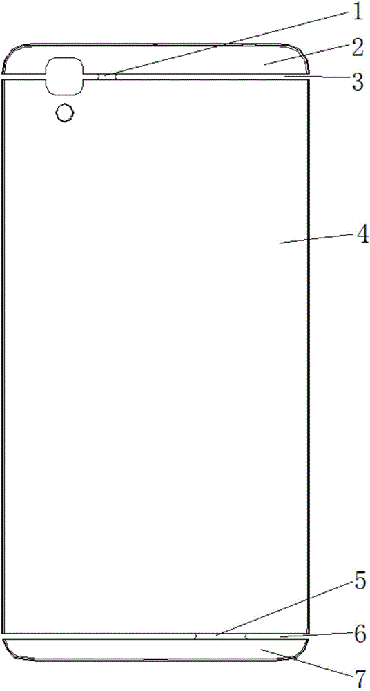
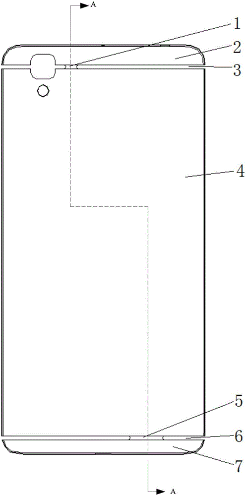
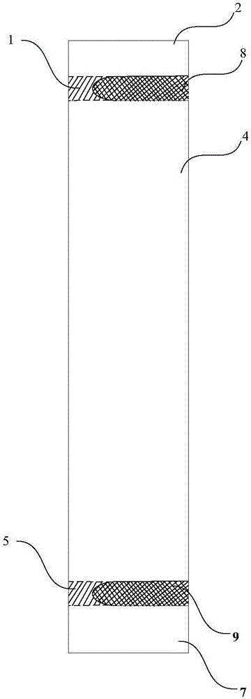
[0035] A casing is provided in an embodiment of the present invention. The casing includes a metal shell and plastic straps. The metal shell is one piece, and the metal shell has a gap and a metal connecting part, and the metal connecting part is integrally formed in the metal shell and is located in the gap. The two ends of the metal connection part are respectively connected to the shell parts of the metal shell on both sides of the gap, and the outer surface of the metal connection part is recessed relative to the outer surfaces of the shell parts on both sides of the gap, that is, the outer surface of the metal connection part and its two sides The shell part of the shell forms a depression, and the inner surface of the metal connection part is recessed relative to the inner surface of the shell parts on both sides of the gap or is flush with the inner faces of the shell parts on both sides of the gap. The plastic tape is filled in the gap, and the plastic tape covers the...

Embodiment 2

[0044] refer to Figure 4 and Figure 5 In this embodiment, the difference from Embodiment 1 is that the first metal connection part 1 is a one-stage metal connection part, and the second metal connection part 5 is a two-stage metal connection part. The one-stage metal connection part is a continuous piece; the two-stage metal connection part includes two spaced apart sub-metal connection parts 51 and 52 located in the same non-signal release area. The length of the one-stage metal connection part is smaller than the length of the two-stage metal connection part, wherein the length of the two-stage metal connection part is the distance between the opposite side edges of the two sub-metal connection parts 51 , 52 . Moreover, the inner surface of the first metal connection part 1 may also be recessed relative to the inner surfaces of the shell parts on both sides of the first slit 3 . The inner surface of the first sub-metal connecting portion 51 may also be recessed relative ...


PUM


Abstract

The invention relates to the field of electronic devices, in particular to a shell, a shell manufacturing method and an electronic device. The shell is provided with a metal connecting part, the metal connecting part is located in a gap and connected to shell parts, on the two sides of the gap, of the metal shell, the outer side face of the metal connecting part sinks relative to the outer side faces of shell parts on the two sides of the gap, the gap is filled with plastic tape, wherein the outer side face of the metal connecting part is covered with the plastic tape. According to the shell, the shell manufacturing method and the electronic device in the embodiment, as the metal connecting part and the plastic tape are combined, firm connection between the shell parts on the two sides of the gap is achieved, and the effect of enhancing the overall strength of the shell is achieved; the metal connecting part is concealed in the plastic tape, and the appearance of the shell is not influenced.

Description

technical field [0001] The invention relates to the field of electronic devices, in particular to a casing, a method for manufacturing the casing, and an electronic device with the casing. Background technique [0002] At present, the casing of an electronic device usually includes a metal casing, and the metal casing has a gap, and the gap is filled with a plastic tape to connect the metal casings on both sides of the gap. However, this connection is not strong enough, so that the overall strength of the casing is not enough. . Contents of the invention [0003] The invention provides a casing with high overall strength. The invention also provides a manufacturing method of the casing. The invention also provides an electronic device with the casing. [0004] The present invention adopts following technical scheme: [0005] One aspect of the present invention provides a shell, including a metal shell, with a gap in the metal shell, and a metal connecting part in the m...

Claims


Application Information

Patent Timeline
IPC IPC(8): H05K5/04
Inventor 许海平
Owner GUANGDONG OPPO MOBILE TELECOMM CORP LTD
Learn More