
Radio frequency circuit and terminal

A radio frequency circuit and circuit generation technology, applied in electrical components, transmitter monitoring, transmission monitoring, etc., can solve problems such as time-consuming and labor-intensive, and achieve the effect of reducing input costs and shortening fault analysis time.

Inactive Publication Date: 2016-12-07
YULONG COMPUTER TELECOMM SCI (SHENZHEN) CO LTD
View PDF2 Cites 47 Cited by
  • Summary
  • Abstract
  • Description
  • Claims
  • Application Information

AI Technical Summary

Problems solved by technology

[0002] If the existing mobile phone fails in the radio frequency channel, it generally needs to be returned to the factory for fault location and detection by maintenance personnel. The maintenance personnel need to use non-signaling tools on the computer, comprehensive testers, network analyzers, etc. fault detection, and usually when analyzing the full Netcom solution, that is, six-mode, eighteen-frequency or more frequency bands, it is necessary to analyze the transmission and reception paths of each frequency band one by one, which is time-consuming and laborious

Method used


Image

  • Radio frequency circuit and terminal
  • Radio frequency circuit and terminal
  • Radio frequency circuit and terminal

Examples


Embodiment Construction

[0033] In order to understand the above-mentioned purpose, features and advantages of the present invention more clearly, the present invention will be further described in detail below in conjunction with the accompanying drawings and specific embodiments. It should be noted that, in the case of no conflict, the embodiments of the present application and the features in the embodiments can be combined with each other.

[0034] In the following description, many specific details are set forth in order to fully understand the present invention. However, the present invention can also be implemented in other ways different from those described here. Therefore, the protection scope of the present invention is not limited by the specific details disclosed below. EXAMPLE LIMITATIONS.

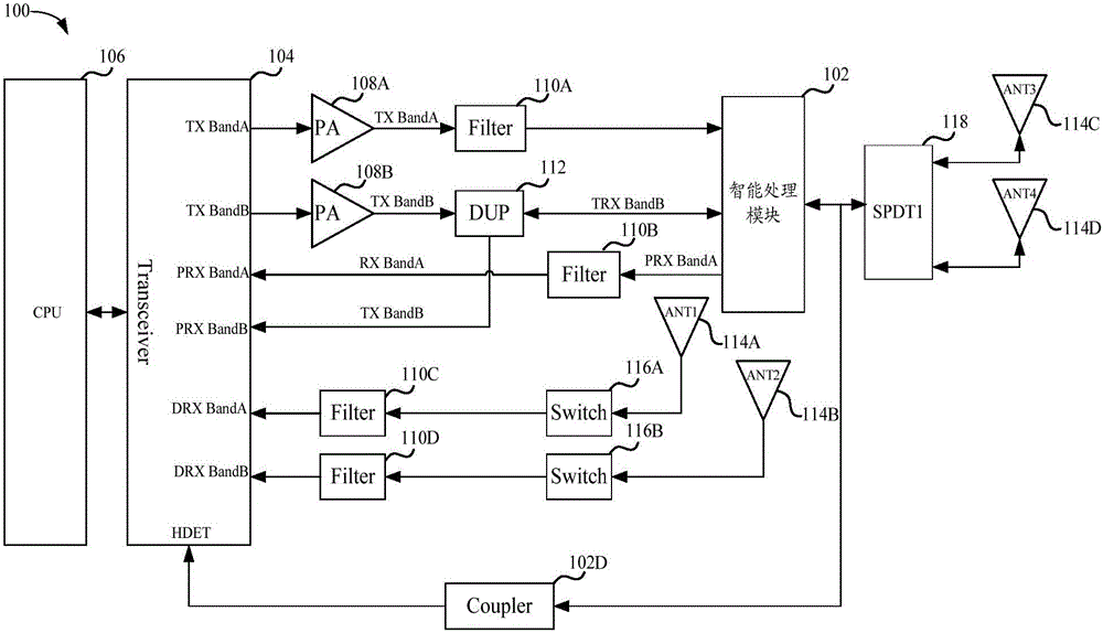
[0035] figure 1 A schematic structural diagram of a radio frequency circuit according to an embodiment of the present invention is shown.

[0036] Such as figure 1 As shown, the radio frequency ci...


PUM


Abstract

The invention provides a radio frequency circuit and a terminal. The radio frequency circuit comprises an intelligent processing module connected to a transceiver for receiving emission signals sent by the transceiver, processing the received emission signals to obtain first detection signals and feeding the first detection signals back to the transceiver; the transceiver used for emitting the emission signals and detecting power values of the received first detection signals; and a processor connected to the transceiver for determining whether an emission pathway for transmitting the emission signals in the radio frequency circuit are abnormal according to the power values of the first detection signals, detected by the transceiver. According to the technical scheme, under the condition that a laboratory test environment is not additionally created, fault detection of the radio frequency circuit is realized, the fault analysis time is shortened, and the investment cost is decreased.

Description

technical field [0001] The present invention relates to the technical field of terminals, in particular, to a radio frequency circuit and a terminal. Background technique [0002] If the existing mobile phone fails in the radio frequency channel, it generally needs to be returned to the factory for fault location and detection by maintenance personnel. The maintenance personnel need to use non-signaling tools on the computer, comprehensive testers, network analyzers, etc. Fault detection, and usually when analyzing the full Netcom solution, that is, six-mode, eighteen-frequency or more frequency bands, it is necessary to analyze the transmission and reception paths of each frequency band one by one, which is time-consuming and laborious. [0003] Therefore, how to realize the fault detection of the radio frequency path without setting up an additional laboratory environment has become an urgent technical problem to be solved. Contents of the invention [0004] Based on at...

Claims


Application Information

Patent Timeline
IPC IPC(8): H04B17/391H04B17/327H04B17/17H04B17/24H04B1/00H04B1/50
CPCH04B1/0064H04B1/0475H04B1/50H04B17/17H04B17/24H04B17/327H04B17/391
Inventor 闫新远
Owner YULONG COMPUTER TELECOMM SCI (SHENZHEN) CO LTD
Learn More