
Single-layer overall wire embedding method for motor stator windings and motor stator

A motor stator and overall technology, applied in the direction of electric components, manufacturing motor generators, prefabricated windings embedded in motors, etc., can solve problems such as low slot fullness, interference, long end of winding structure, etc., to improve slot fullness , reasonable structure and easy operation

Inactive Publication Date: 2016-12-07
CSR ZHUZHOU ELECTRIC CO LTD
View PDF8 Cites 2 Cited by
  • Summary
  • Abstract
  • Description
  • Claims
  • Application Information

AI Technical Summary

Problems solved by technology

[0011] The purpose of the present invention is to solve the problems that the slot fullness rate of the motor windings in the existing motor stator windings is not very high, and the ends of the upper and lower layered winding structures are longer, and there will be interference between them, and proposes A new motor stator winding embedding method, which can not only realize the overall coil embedding, but also improve the slot filling rate of the embedding wire, and can also greatly shorten the end size of the winding structure, improve the motor overall performance of

Method used


Image

  • Single-layer overall wire embedding method for motor stator windings and motor stator
  • Single-layer overall wire embedding method for motor stator windings and motor stator
  • Single-layer overall wire embedding method for motor stator windings and motor stator

Examples


Embodiment 1

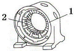
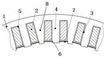
[0036] as attached figure 1 and 2 As shown, a motor stator, which is an annular outer stator, includes a stator core 1 and a winding 2. It is characterized in that the wire slot 3 of the stator core is an open slot, and the wire teeth 4 are equal-width teeth ; The winding 2 is an integrally formed winding; each integrally formed winding is integrally sleeved on the embedded wire teeth of a stator core, and the integrally formed winding is a single-layer structure in the embedded wire groove of the stator core, On the top of the equal-width teeth of the stator core, there is a slot wedge installation slot 6 at the side port of the embedding slot. The slot wedge 7 is inserted in the slot wedge installation slot 6, and the annular integrally formed winding is prevented from falling by the slot wedge 7. The integrally embedded winding is made of self-adhesive enameled wire, which is initially wound into a winding through a mold, and then the winding is shaped and fixed by a mold ...

Embodiment 2

[0048] The basic principle of embodiment two is the same as embodiment one, but the structure is different (as attached image 3 shown); a motor stator, which is an annular inner stator structure, including a stator core 201 and a stator winding 202, and a motor stator opening slot 203 with an equal-width tooth structure on the stator core 201; the motor stator opening is inlaid The wire groove is a trapezoidal opening wire groove with a narrow slot width and a narrow bottom, and the stator wire teeth 204 formed on the motor stator are equal-width teeth through the motor stator opening wire groove; 202 is an integrally formed winding, which is sleeved on the equal-width teeth of the stator core, so that the integrally formed winding is just embedded in the opening embedding groove of the motor stator.

[0049] The integrally formed windings 202 are wound into a centralized structure with a pitch of 1 through a mold. Each set of integrally formed windings is placed on the equal...

Embodiment 3

[0062] The basic principle of the third embodiment is the same as that of the first embodiment. It is a motor stator, which is an annular outer stator structure, including a stator core and a stator winding. There is a motor stator with an equal-width tooth structure on the stator core; The stator opening slot of the motor described above is a rectangular opening slot having the same width as the bottom of the lower slot, and the stator slot teeth formed on the motor stator are equal-width teeth through the opening slot of the motor stator. ; The stator winding is an integrally formed winding, and the integrally formed winding is set on the equal-width teeth of the stator core, so that the integrally formed winding is just embedded in the opening embedding slot of the motor stator.

[0063] The integrally formed windings are wound into a centralized structure with a pitch of 1 through a mold. Each set of integrally formed windings is placed on the equal-width teeth of a stator ...


PUM


Abstract

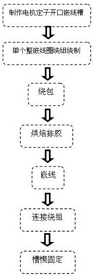
The invention provides a single-layer overall wire embedding method for motor stator windings. Overall embedding molding windings are wrapped with enamelled wires; motor stator open wire embedding slots with equal-width tooth structures are manufactured on an iron core of a motor stator; stator wire embedding teeth formed on the motor stator are equal-width teeth; and the overall embedding molding windings are embedded into the motor stator open wire embedding slots in a single-layer overall embedding manner. The overall embedding molding windings are directly embedded into the open slots as a whole. The equal-width tooth structures and the single-layer overall embedding molding windings are adopted, and fixing and molding are carried out through a mold, so that the windings become the overall embedding molding windings; the wires of the windings can be tightly attached together; and the problems of intersection and interference among the windings can be effectively solved. The end parts of the windings are relatively short, so that the wire embedding technology is greatly simplified; the space filling factor can reach over 90%; the overall embedding molding windings are reasonable in structure; and the mechanical strength is higher than that of dispersedly embedded coils.

Description

technical field [0001] The invention relates to a manufacturing method of motor components, in particular to a method for embedding wires of motor stator windings, which is mainly used for embedding wires of motor stator windings; it belongs to the technical field of motor manufacturing. Background technique: [0002] The motor is formed by a combination of a stator and a rotor, where the motor stator is the stationary part of the motor. The stator is composed of three parts: stator core, stator winding and frame or mandrel. The stator winding of the motor stator can be divided into two types: centralized and distributed according to the shape of the coil winding and the way of embedded wiring. According to the different arrangements of embedded wiring, distributed windings can be divided into two types: concentric and stacked. [0003] (1) Concentric winding: Concentric winding is several rectangular coils of different sizes in the same coil group, which are arranged one ...

Claims


Application Information

Patent Timeline
Patent Type & Authority Applications(China)
IPC IPC(8): H02K15/06
CPCH02K15/066H02K2213/03
Inventor 王冬梅朱利湘晏才松翁萍刘焕
Owner CSR ZHUZHOU ELECTRIC CO LTD
Learn More