
Tab cooling structure of battery pack, battery pack and vehicle with battery pack

A technology for cooling structures and battery packs, applied in battery pack components, small-sized batteries/battery packs, secondary batteries, etc., can solve the problems of poor heat dissipation, high cost, and poor space utilization.

Active Publication Date: 2016-12-07
FAFA AUTOMOBILE (CHINA) CO LTD
View PDF6 Cites 10 Cited by
  • Summary
  • Abstract
  • Description
  • Claims
  • Application Information

AI Technical Summary

Problems solved by technology

[0003] At present, in the field of new energy electric vehicles, the cooling methods of the power battery pack system mainly include natural cooling, air cooling and liquid cooling. The heat dissipation of the bottom surface of the group or one of the other surfaces, for the liquid-cooled heat dissipation on the surface of each battery cell, the heat dissipation effect is the best, but the cost is high, the space utilization rate is poor, and the reliability is poor
The heat dissipation based on the bottom surface of the module or another surface is easy to implement and low in cost, and the space utilization rate is relatively high, but the heat dissipation effect is relatively poor

Method used


Image

  • Tab cooling structure of battery pack, battery pack and vehicle with battery pack
  • Tab cooling structure of battery pack, battery pack and vehicle with battery pack
  • Tab cooling structure of battery pack, battery pack and vehicle with battery pack

Examples


Embodiment Construction

[0032] Various exemplary embodiments of the present disclosure will be described in detail below with reference to the accompanying drawings. It should be understood, however, that the description of various embodiments is illustrative only and not intended to limit any limitation to the disclosed technology.

[0033] The terms used herein are for describing specific embodiments only, and are not intended to limit the present disclosure. As used herein, "a," "a," and "the" in the singular are intended to include the plural forms as well, unless the context clearly dictates otherwise. It should also be understood that when the word "comprising" is used herein, it indicates the presence of the indicated features, integers, steps, operations, units and / or components, but does not exclude the presence or addition of one or more other features, whole, steps, operations, units and / or components and / or combinations thereof.

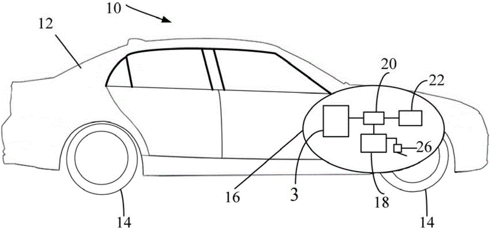
[0034] now refer to figure 1 , figure 1 A schematic si...


PUM


Abstract

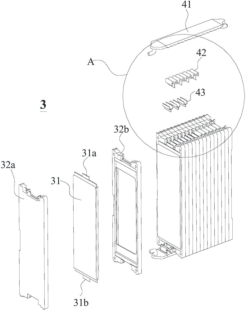
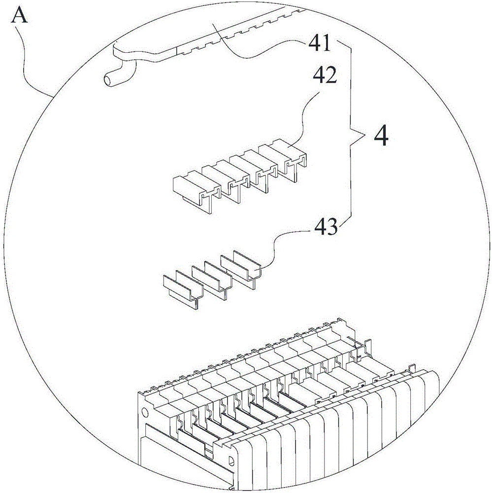
The invention provides a tab cooling structure of a battery pack, the battery pack and a vehicle with the battery pack. The tab cooling structure of the battery pack comprises tab connection pieces, insulating heat conduction blocks and liquid cooling plates, wherein the tab connection pieces are electrically connected with tabs of every two adjacent battery cells of the battery pack; clamping slots are formed in the insulating heat conduction blocks, and provided with first surfaces and second surfaces which are parallel to each other, and third surfaces connected with the first surfaces and the second surfaces; furthermore, connection parts, connected with the tabs of the battery cells, of the tab connection pieces are clamped in the clamping slots, so that at least the first surfaces and the second surfaces are respectively in surface contact with the two opposite side surfaces of the connection parts, and heat generated by the tabs can be exported to the insulating heat conduction blocks; the liquid cooling plate is in surface contact with the insulating heat conduction blocks; meanwhile, cooling liquid can flow through the liquid cooling plate to cool the insulating heat conduction blocks. The invention further provides the battery pack with the tab cooling structure and the vehicle with at least one battery pack.

Description

technical field [0001] The present disclosure relates to a battery pack tab cooling structure, a battery pack having the battery pack tab cooling structure, and a vehicle having at least one of the battery packs. Background technique [0002] In today's world, vehicles have become an indispensable means of transportation for people's work and life. With the shortage of oil resources, the improvement of environmental protection requirements and the development of technology, more and more vehicles are driven by using electric energy in whole or in part. more common. [0003] At present, in the field of new energy electric vehicles, the cooling methods of the power battery pack system mainly include natural cooling, air cooling and liquid cooling. The heat dissipation of the bottom surface of the group or one of the other surfaces, for the liquid cooling of the surface of each battery cell, has the best heat dissipation effect, but the cost is high, the space utilization rate...

Claims


Application Information

Patent Timeline
IPC IPC(8): H01M2/30H01M10/613H01M10/625H01M10/6554H01M10/6567H01M50/553H01M50/566
CPCH01M10/613H01M10/625H01M10/6554H01M10/6567H01M50/543Y02E60/10
Inventor 师绍纯许晶王英刘文鹏杜兢
Owner FAFA AUTOMOBILE (CHINA) CO LTD
Learn More