Head-mounted optical system for observing 3D display of large-sized screen

An optical system, large-scale technology, applied in optics, optical components, instruments, etc., can solve the problems of discounted 3D high-definition video experience, poor 3D effect, and low immersion.

Inactive Publication Date: 2016-12-07
MIKOLTA OPTICAL TECH CO
View PDF13 Cites 8 Cited by
  • Summary
  • Abstract
  • Description
  • Claims
  • Application Information

AI Technical Summary

Problems solved by technology

[0005] With the popularization of smart phones, most of the smart phones currently also support the playback of 3D video and images, but if the mobile phone is directly used as a display platform for watching 3D video, the 3D effect is not good due to the small screen of the mobile phone. 3D glasses watching 3D videos on smartphones for a long time will cause vision damage, and cause dizziness, vertigo, nausea and other adverse effects
Moreover, with regard to the head-mounted stereoscopic viewing devices based on mobile phone screens in the existing market, when 3D split-screen display is performed, the maximum display effect that can be achieved technically is only half of the resolution of the mobile phone. The screen is 1080P, and the maximum split-screen 3D display effect achieved is only 540P, which means that the user's 3D high-definition video experience will be greatly reduced
At the same time, due to the limitations of the size of the mobile phone screen itself, when the mobile phone displays a 16:9 dual screen in 3D, the utilization rate of the mobile phone screen is inevitably relatively low, and the video images displayed on the dual screen in the mobile phone are also relatively small, which will directly In the process of 3D viewing, the virtual picture is relatively small and the sense of immersion is low.

Method used


Image

  • Head-mounted optical system for observing 3D display of large-sized screen
  • Head-mounted optical system for observing 3D display of large-sized screen
  • Head-mounted optical system for observing 3D display of large-sized screen

Examples


Embodiment 1

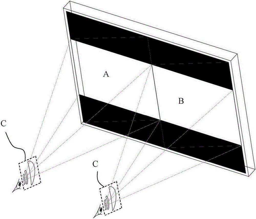
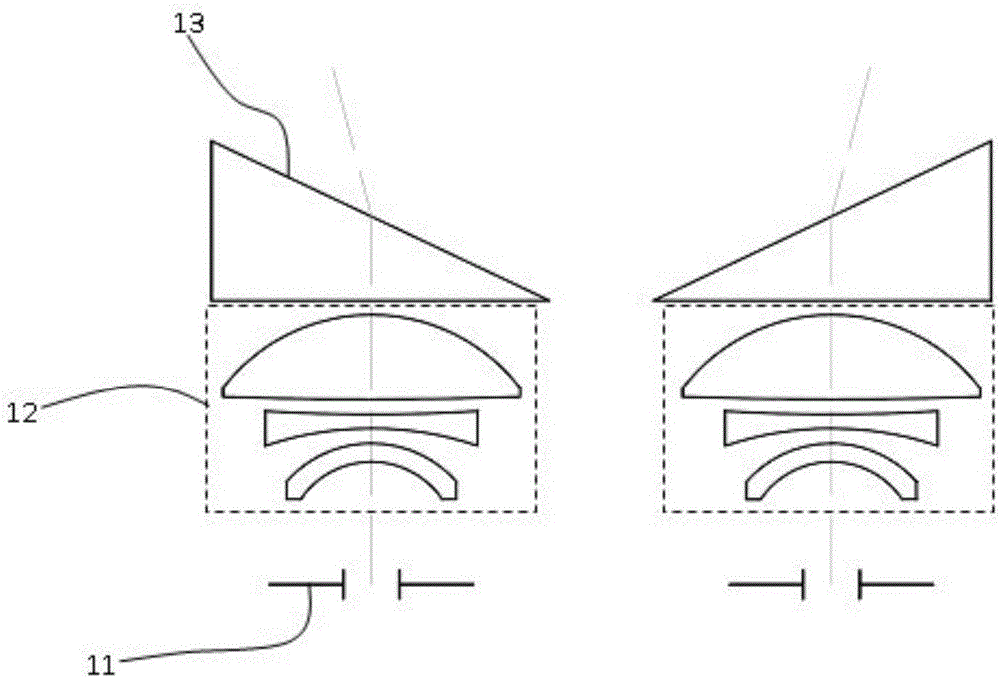
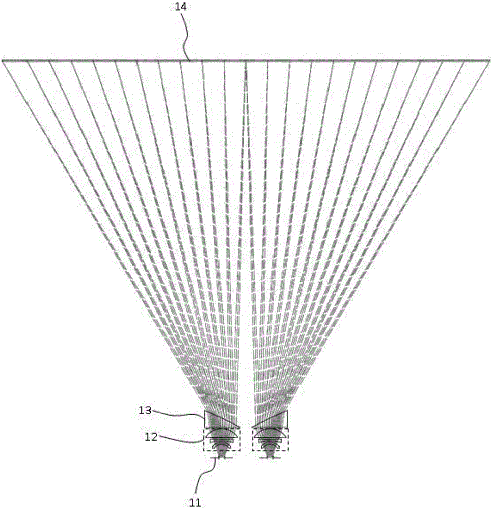
[0064] The structural sectional view of the head-mounted optical system of this embodiment is as follows: figure 2 As shown, its light path diagram is shown as image 3 shown. The head-mounted optical system is made up of eye pupil 11 , eyepiece group 12 , deflection prism 13 , and display screen 14 . The pupil 11 of a normal person has a pupil size of 2-4mm during the day and 5-7mm at night, which shrinks and enlarges with the intensity of the light. In this embodiment, the diameter is preferably 4mm. The distance from the eye pupil 11 to the first lens is 10-18 mm, preferably 10 mm in this embodiment. Described display screen 14, present embodiment preferably it is the display screen that diagonal line is 32 inches, and it is made up of sub-screens on left and right sides, and the length of the diagonal line of each sub-screen is 400mm (that is, like circle radius is 200mm) , and its display wavelength is 460nm, 550nm, 520nm; Its distance to the last deflection prism 13 ...

Embodiment 2

[0073] The sectional view of the head-mounted optical system of this embodiment is as follows: Figure 8 As shown, its light path diagram is shown as Figure 9 mentioned. The position of its eye pupil 11, the composition of eyepiece group 12, and the distance and the size of display screen 14 are completely consistent with those in embodiment 1, but deflection prism 13 is changed into ruled Fresnel lens 23 in embodiment 1 .

[0074] Described eye pupil 11, the present embodiment preferably its diameter is 4mm. The distance from the pupil 11 to the first eyeglass is 10mm in this embodiment. Described display screen 14, present embodiment preferably it is the display screen of 32 inches, and it is made up of sub-screens on the left and right sides, and the length of the diagonal line of each sub-screen is 400mm (that is, the radius of a circle is 200mm), and it shows The wavelength is 460nm, 550nm, 520nm; the distance from it to the last deflecting prism 13 is 400-700mm, and...

Embodiment 3

[0077] In the head-mounted optical system of this embodiment, the thicker convex lens in the eyepiece group can be changed to a thinner annular Fresnel lens, so as to reduce the thickness of the eyepiece group while ensuring the optical power. The sectional view of the optical system of this embodiment is as follows Figure 10 As shown, its light path diagram is shown as Figure 11 Said, it is made up of eye pupil 11, eyepiece group 32, deflection prism 33 and display screen.

[0078] Described eye pupil 11, the present embodiment preferably its diameter is 4mm. The distance from the pupil 11 to the first lens is preferably 10mm in this embodiment. Described display screen, present embodiment preferably it is the display screen of 32 inches, and it is made up of sub-screens on the left and right sides, and the length of the diagonal line of each sub-screen is 400mm (that is, the image circle radius is 200mm), and its display wavelength It is 460nm, 550nm, 520nm; Its distanc...


PUM


Abstract

The invention relates to a head-mounted optical system for observing 3D display of a large-sized screen. The head-mounted optical system comprises 3D imaging modules corresponding to eye pupils, wherein each 3D imaging module comprises a light path turning module and a picture amplification module and is used or amplifying the pictures of the large-sized screen into the eye pupils. The head-mounted optical system combines with the light path turning modules and the picture amplification modules to make the centers of the eye pupils on the left and right sides seed the pictures of the large-sized screen, makes the pictures seen by the left and right eyes of an observer completely coincide and brings a high-definition 3D visual effect experience.

Description

technical field [0001] The invention relates to a head-mounted optical system, in particular to a head-mounted optical system for observing 3D display on a large-size screen. Background technique [0002] Head-mounted virtual reality displays were originally mainly used in the military (such as helmet sights, military training simulators). Due to the development of 3D display technology (including 3D movies and 3D games), as well as virtual reality (VR) and augmented reality (AR) technologies, head-mounted virtual reality displays are becoming more and more popular. The current head-mounted virtual reality display is in a state of explosive development. In the future, the 3C integration of smart homes will develop rapidly (that is, the integration of computers, communications, and consumer electronics). All can be controlled by smart phone applications] it will get more rapid development. [0003] The principle of the 3D display of the head-mounted virtual reality display ...

Claims


Application Information

Patent Timeline
Patent Type & Authority Applications(China)
IPC IPC(8): G02B27/01G02B27/22
CPCG02B27/0172G02B30/36G02B2027/0116G02B2027/0134
Inventor 郎欢标
Owner MIKOLTA OPTICAL TECH CO
Why Eureka
Try Eureka