
External radiation source radar-based direct wave signal purification method

A technology of external radiation source radar and direct wave signal, which is applied in the field of radar, can solve the problems of gain loss, residual clutter, detection of false targets, etc., and achieve the effect of avoiding deviation, effectively detecting and eliminating false targets

Active Publication Date: 2016-12-07
XIDIAN UNIV
View PDF6 Cites 6 Cited by
  • Summary
  • Abstract
  • Description
  • Claims
  • Application Information

AI Technical Summary

Problems solved by technology

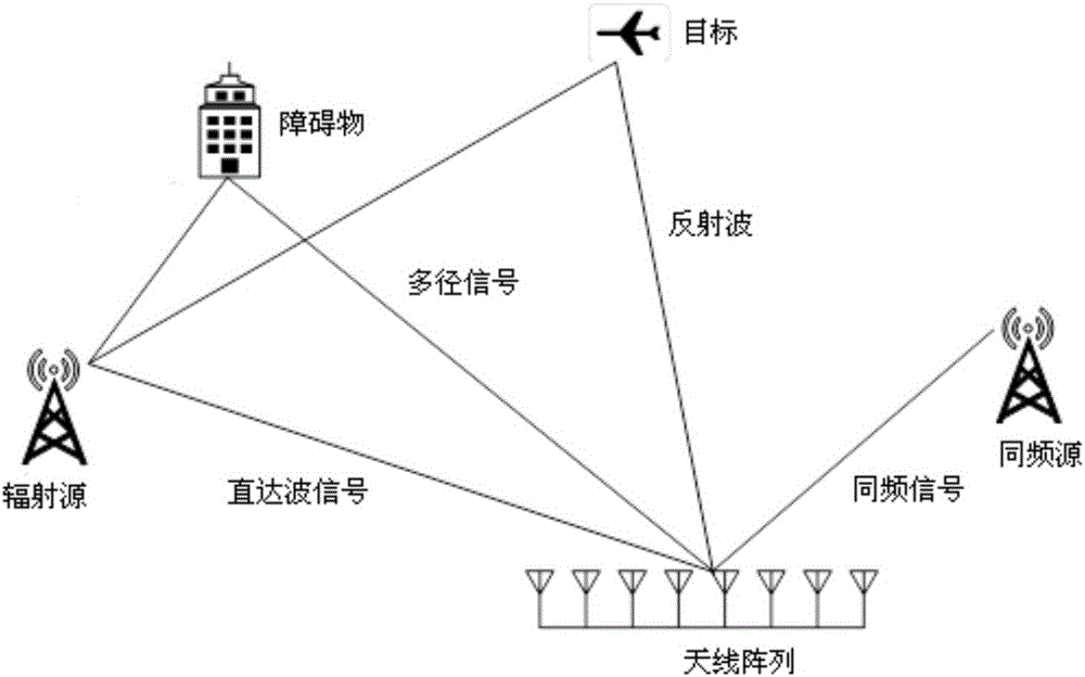
However, in practical applications, due to the complex environment of the target and the presence of the same frequency signal of the radiation source signal in the space, the direct wave signal received by the reference channel is not a pure signal, and may contain strong multiple Interference signals such as path signals and same-frequency signals
On the one hand, the existence of these interfering signals will cause deviations in the construction of the direct wave delay matrix, resulting in incomplete clutter suppression and resulting in residual clutter
On the other hand, interfering signals also cause the loss of accumulated gain during range-Doppler processing
However, the residual clutter and the loss of accumulated gain will cause deviations in the estimation of target parameters, which will lead to the failure of the external radiation source radar to detect the target or the detection of false targets

Method used


Image

  • External radiation source radar-based direct wave signal purification method
  • External radiation source radar-based direct wave signal purification method
  • External radiation source radar-based direct wave signal purification method

Examples


Embodiment Construction

[0019] The following will clearly and completely describe the technical solutions in the embodiments of the present invention with reference to the accompanying drawings in the embodiments of the present invention. Obviously, the described embodiments are only some, not all, embodiments of the present invention. Based on the embodiments of the present invention, all other embodiments obtained by persons of ordinary skill in the art without making creative efforts belong to the protection scope of the present invention.

[0020] In addition, in order to clearly describe the technical solutions of the embodiments of the present invention, in the embodiments of the present invention, words such as "first" and "second" are used to distinguish the same or similar items with basically the same function and effect, Those skilled in the art can understand that the words "first", "second", etc. do not limit the quantity and execution order.

[0021] For ease of understanding, the follo...


PUM


Abstract

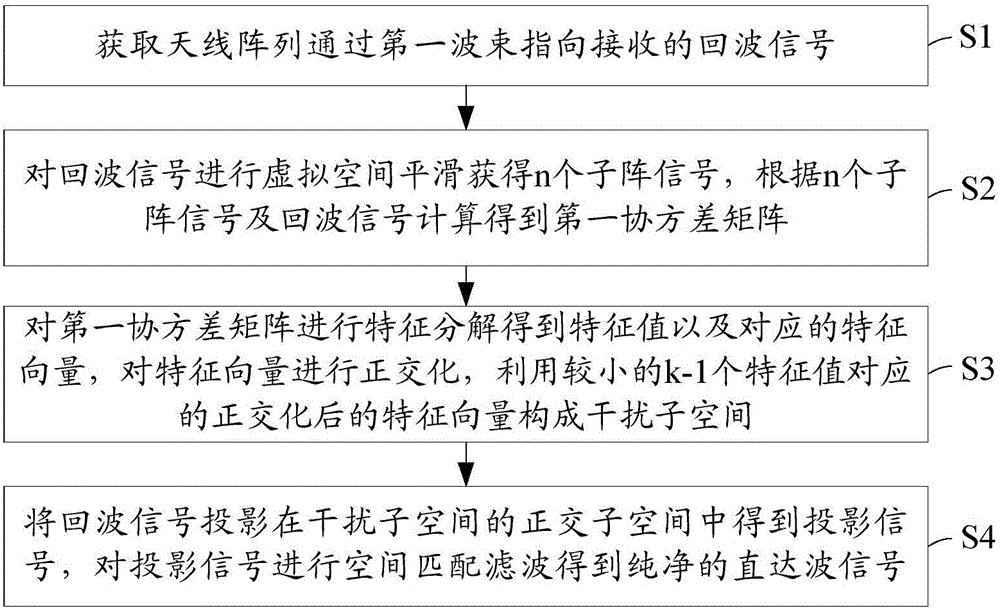
The invention belongs to the radar technical field and discloses an external radiation source radar-based direct wave signal purification method. The method includes the following steps that: echo signals received by an antenna array through a first wave beam pointer are acquired; virtual space smoothing is performed on the echo signals, so that n sub-array signals can be obtained, a first covariance matrix is calculated according to the n sub-array signals and the echo signals; eigenvalue decomposition is performed on the first covariance matrix, so that eigenvalues and corresponding eigenvectors can be obtained, orthogonalization is performed on the eigenvectors, and orthogonalized eigenvectors corresponding to small k-1 eigenvalues are utilized to constitute an interference subspace; and the echo signals are projected onto the orthogonal subspace of the interference subspace, so that projection signals can be obtained, and spatial matched filtering is performed on the projection signals, so that pure direct wave signals can be obtained. With the external radiation source radar-based direct wave signal purification method of the invention adopted, the direct wave signals can be can purified, and deviation caused by target parameter estimation due to the impurity of the direct wave signals can be avoided, false targets are eliminated, and effective detection on a target can be realized.

Description

technical field [0001] The invention relates to the field of radar technology, in particular to a method for purifying direct wave signals based on external radiation source radar. Background technique [0002] The external radiation source radar itself does not radiate electromagnetic signals, but uses the existing radiation source signals in space as the radiation source to detect, locate and track targets in the air. It relies on the characteristics of passive detection, simple structure, and low cost Features such as low cost and anti-stealth have received extensive attention. [0003] In the process of radar signal processing, the direct wave signal received by the reference channel of the external radiation source radar is very important. It is not only used for the construction of the direct wave delay matrix in the process of clutter suppression, but also used as the Reference signal during Doppler processing. However, in practical applications, due to the complex ...

Claims


Application Information

Patent Timeline
Patent Type & Authority Applications(China)
IPC IPC(8): G01S7/41
CPCG01S7/414
Inventor 王俊陈刚苏思元
Owner XIDIAN UNIV
Learn More