Air supply equipment and its perforated plate

A perforated plate and air hole technology, which is applied in lighting and heating equipment, ventilation systems, space heating and ventilation, etc. The effect of improving the performance, improving the air supply efficiency, and reducing the pressure difference between the front and rear

Active Publication Date: 2022-03-25
GREE ELECTRIC APPLIANCES INC
View PDF7 Cites 0 Cited by
  • Summary
  • Abstract
  • Description
  • Claims
  • Application Information

AI Technical Summary

Problems solved by technology

[0003] In the existing perforated plate, the opening form of the microhole is generally a through hole with a constant diameter. This opening method makes the air flow through the through hole encounter greater resistance and higher pressure loss, which not only restricts the delivery of the perforated plate. The wind efficiency also adversely affects the comfort of the air supply during the use of the equipment

Method used


Image

  • Air supply equipment and its perforated plate
  • Air supply equipment and its perforated plate

Examples


Embodiment Construction

[0018] The core of the present invention is to provide a perforated plate with high air supply efficiency and better air supply comfort; meanwhile, to provide an air supply device using the above-mentioned perforated plate.

[0019] In order to make those skilled in the art better understand the solution of the present invention, the present invention will be further described in detail below with reference to the accompanying drawings and specific embodiments.

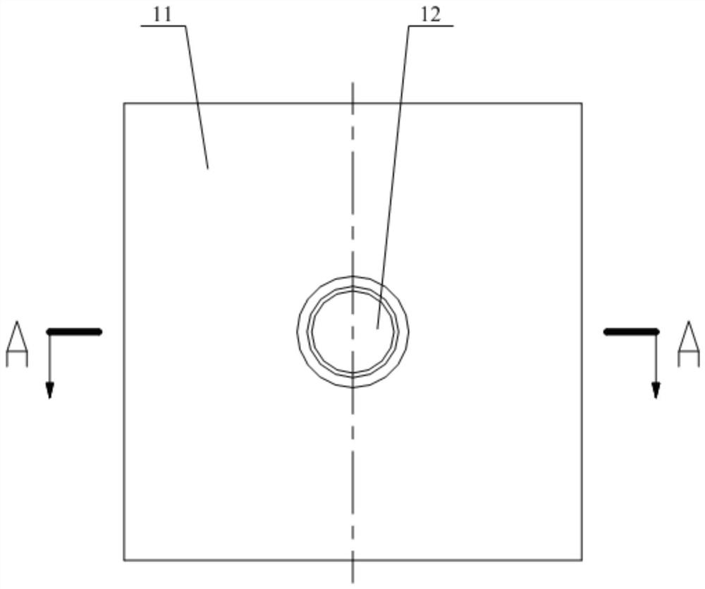
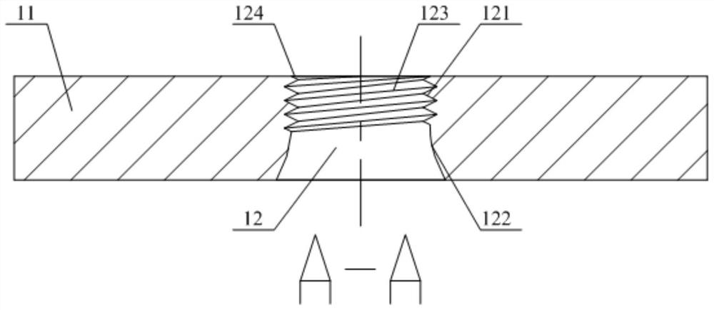
[0020] Please refer to figure 1 and figure 2 , figure 1 A schematic structural diagram of a porous plate provided by a specific embodiment of the present invention; figure 2 for figure 1 A cross-sectional view of the structure in the direction A-A.

[0021] In a specific embodiment, the perforated plate provided by the present invention includes a plate body 11, and the plate body 11 has a plurality of air holes 12 penetrating along its thickness direction. Section 122, the diameter of the air outlet section 12...


PUM


Abstract

The invention discloses a porous plate, comprising a plate body, the plate body has a number of air holes penetrating along its thickness direction, the air holes include an air inlet section and an air outlet section arranged in sequence along the air flow direction, the air outlet section The segments gradually increase in diameter along the airflow direction. During the operation of the equipment, the air flow enters from the air inlet end of the air hole, and then enters the air supply section through the air inlet section. Since the air supply section has a structure of variable diameter and gradual expansion, the air flow pressure at the air outlet end of the air hole is effectively reduced, so that the perforated plate The pressure difference between the front and back of the air compressor is correspondingly reduced, and at the same time, the air supply resistance is effectively reduced, the air supply efficiency is improved, and the comfort of the air supply process is correspondingly improved. The invention also discloses an air supply device using the perforated plate.

Description

technical field [0001] The invention relates to the technical field of matching components of HVAC equipment, in particular to a perforated plate. The invention also relates to an air supply device using the perforated plate. Background technique [0002] At present, perforated plates are widely used in many fields such as medical treatment, transportation, industry and HVAC. The porous structure can reduce the aerodynamic noise generated by the equipment, and can filter out impurities as a filter device. In passenger cars, medical operating rooms, offices and air conditioners, the high-speed airflow can be rectified into a confluent jet with low speed and low turbulence, so that people can not feel the obvious blowing feeling and improve the comfort of air supply. [0003] In the existing perforated plate, the opening form of the micropore is generally a through hole with a constant diameter. This opening method makes the resistance and pressure loss encountered when the a...

Claims


Application Information

Patent Timeline
Patent Type & Authority Patents(China)
IPC IPC(8): F24F7/00F24F13/28F24F13/08
CPCF24F7/00F24F13/085F24F13/28
Inventor 赵万东彭勃李建建熊军高旭
Owner GREE ELECTRIC APPLIANCES INC
Why Eureka
Try Eureka