A combined spring sleeve assembly for aircraft wheels

A spring sleeve and combined technology, which is applied in the direction of spring/shock absorber, coil spring, mechanical equipment, etc., can solve the problems that the piston cannot be reset, the hidden danger of accidents, and the brake cannot be completely released, so as to reduce the number of parts, operate reliably, The effect of improving product technical performance and economy

Inactive Publication Date: 2019-01-11
XIAN AVIATION BRAKE TECH
View PDF4 Cites 0 Cited by
  • Summary
  • Abstract
  • Description
  • Claims
  • Application Information

AI Technical Summary

Problems solved by technology

Once the spring sleeve is loose, the piston cannot be reset after the brake is released, so the brake cannot be completely released, which will cause accidents

Method used


Image

  • A combined spring sleeve assembly for aircraft wheels
  • A combined spring sleeve assembly for aircraft wheels

Examples


Embodiment 1

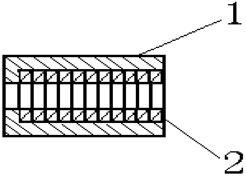
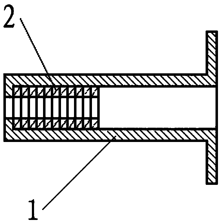
[0016] The utility model relates to a sleeve-combined spring sleeve assembled on a pull rod of a gap adjustment mechanism, which is used for automatic gap adjustment of aircraft wheels. The spring sleeve is composed of a sleeve 1 and a spring sleeve 2 . Sleeve 1 is a hollow rotating body, one end is open, and the other end has an end plate, which forms the shoulder of the spring sleeve, cooperates with the inner end surface of the spring sleeve 2, and is used to transmit and overcome the clamping of the spring sleeve during work. The action force of the force on the brake; the inner cavity of the sleeve 1 is used to accommodate the spring sleeve 2 assembled on the pull rod of the gap adjustment mechanism; the inner diameter of the sleeve 1 matches the outer diameter of the spring sleeve, and limits the outer diameter of the spring sleeve expansion, loosening, so as not to reduce the clamping force. The center of the shoulder of the sleeve 1 has a through hole matched with the...

Embodiment 2

[0026] The utility model relates to a sleeve-combined spring sleeve assembled on a pull rod of a gap adjustment mechanism, which is used for automatic gap adjustment of aircraft wheels. The spring sleeve is composed of a sleeve 1 and a spring sleeve 2 .

[0027] The composition of this embodiment, the matching requirements between the sleeve 1 and the spring sleeve 2 of this embodiment, and the materials are the same as those of the first embodiment.

[0028] The difference between this embodiment and Embodiment 1 is that the outer circumferential surface of the open end of the sleeve 1 has a radially protruding flange, which forms a fixed seat for the return spring in the wheel return mechanism that cooperates with it. , when this embodiment cooperates with the return force mechanism, the return force spring in the return force mechanism is set on the sleeve, and one end surface of the return force spring is against the end surface of the flange at the open end of the sleeve,...


PUM


Abstract

The invention discloses a combined spring sleeve. The combined spring sleeve consists of a sleeve and a spring sleeve. The spring sleeve is positioned in the sleeve. The spring sleeve is pressed in an inner cavity of the sleeve, and is in interference fit with the same. A through hole for mounting in a pull rod is formed in the center of a stop shoulder of the sleeve, so that the pull rod penetrates through the through hole to extend in the sleeve, and is matched with an inner hole of the spring sleeve in the sleeve. When the combined spring sleeve is matched with a machine wheel force return mechanism, a flange is radially projected on the outer peripheral surface of the opening end of the sleeve; and the flange forms a fixed base of a force return spring in the matched machine wheel force return mechanism. In the combined spring sleeve, the spring sleeve is restrained by the sleeve, so that the deformation of the spring sleeve in operation is limited, and the stress state is stable; and the combined spring sleeve has the characteristics of simple and compact structure, stable wrapping force, no or less attenuation of pullout force, high production pass percent and reliable operation, and effectively overcomes the potential safety hazards caused by unstable wrapping force and loose use in the prior art.

Description

technical field [0001] The invention relates to the field of aircraft wheel braking devices, in particular to an automatic gap adjustment mechanism part of an aircraft wheel braking device. Background technique [0002] In order to meet the braking performance requirements of modern aircraft, the aircraft wheel is equipped with an automatic gap adjustment mechanism. Its function is that after the aircraft has repeatedly landed and braked, the distance between the piston and the pressure plate increases due to the wear of the brake friction material. In order to ensure the braking performance and improve the braking sensitivity, the mechanism can automatically adjust the gap between the piston and the pressure plate to meet the specified requirements. The automatic gap adjustment mechanism has various structural types, and the spring sleeve type automatic gap adjustment mechanism is one of them. It is mainly composed of a spring sleeve and a pull rod. The pull rod is insta...

Claims


Application Information

Patent Timeline
Patent Type & Authority Patents(China)
IPC IPC(8): F16D65/40F16F1/12B64C25/42
CPCB64C25/42F16D65/40F16F1/12
Inventor 何永乐王宏儒张万顺龙晓军
Owner XIAN AVIATION BRAKE TECH
Why Eureka
Try Eureka