A kind of extensible lifting equipment balance weight mechanism
A lifting equipment and counterweight technology, applied in cranes and other directions, can solve the problems that mobile counterweight tower cranes have not been well developed and applied, the development cost of movable counterweight is high, and the moving distance of mobile counterweight is limited. Achieve the effect of facilitating the layout of the tower crane construction site, reducing the influence of adverse torque, and preventing the boom from tilting back.
- Summary
- Abstract
- Description
- Claims
- Application Information
AI Technical Summary
Problems solved by technology
Method used
Image
Examples
Embodiment 1
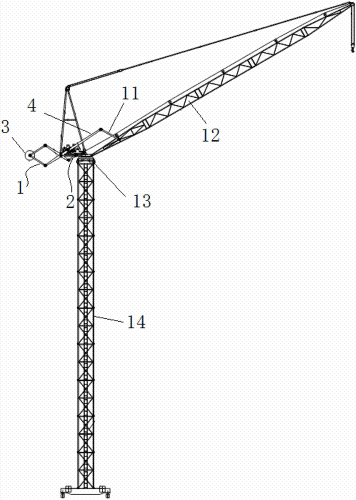
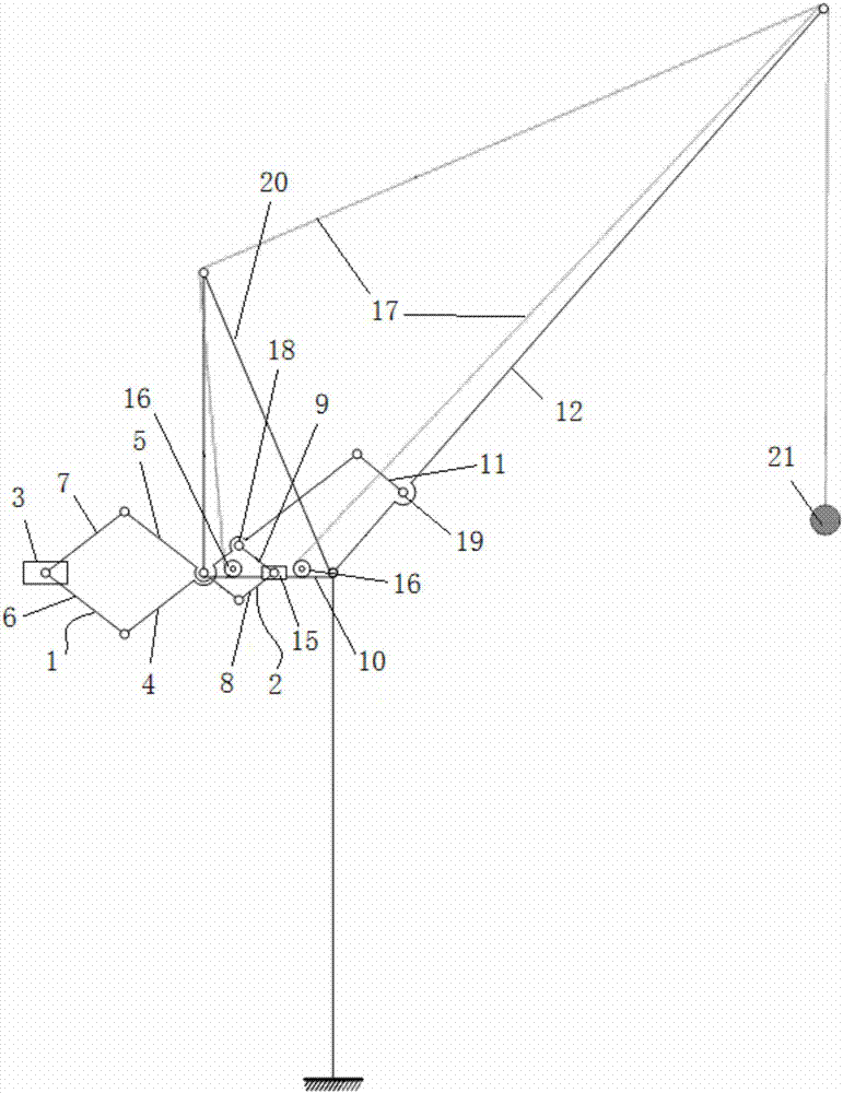
[0055] The hoisting equipment in this embodiment is a tower crane, such as Figure 1~4 As shown, in this embodiment, the hinged ends of the third connecting rod 8 and the fourth connecting rod 9 are slidably connected to the balance arm 10, wherein the hinged ends of the third connecting rod 8 and the fourth connecting rod 9 are provided with There is a slide block 15, which is provided with a slide rail on the balance arm 10, and the slide block 15 moves along the slide rail. This embodiment is provided with a support rod 11, and the drive scissor assembly in the The first scissor bar 4 is provided with an inner extension hinge point 18, such as image 3 As shown, the third connecting rod 8 is hinged to the second scissor bar 5 in the driving scissors assembly, and the fourth connecting rod 9 is hinged to the inner extension hinge on the first scissor bar 4 At point 18, the free end of the first scissor bar 4 is connected to the boom 12 through the support bar 11, and the tw...
Embodiment 2
[0061] The hoisting equipment in this embodiment is a port crane, such as Figure 9 As shown, the main body of the boom 12 of the port crane in the prior art includes a four-link structure, wherein the end hinges of the first boom rod 23 and the second boom rod 24 form a boom link Hinge point 25.
[0062] like Figure 10 As shown, in this embodiment, the first boom rod 23 and the second boom rod 24 form a scissor mechanism, and the hinge of the first boom rod 23 and the second boom rod 24 A boom connecting rod hinge point 25 is formed, and the boom connecting rod hinge point 25 is arranged at the connecting end of the balance arm 10 and the tower body 14, wherein the first boom rod 23 exceeds the boom connecting rod The extension part of the hinge point 25 is the third connecting rod 8 connected with the driving scissors assembly, and the extension part of the second boom rod 24 beyond the hinge point 25 of the boom connecting rod is the connecting rod 8 connected with the d...
Embodiment 3
[0066] like Figure 11 As shown, the difference between this embodiment and Embodiment 2 is that the jib 12 in this embodiment only includes a four-bar linkage mechanism without other structures, and the wire rope goes around the end of the four-bar linkage mechanism away from the tower body 14. Connect with hoisting weight 21 behind the pulley.
[0067] The working principle of this embodiment is:
[0068]When the first boom rod 23 swings, it drives the hoisting weight 21 to move on the one hand, and drives the driving scissors assembly to open and close on the other hand, and then drives the balance weight 3 to move telescopically.
PUM
 Abstract
Description
Claims
Application Information
 - R&D
- Intellectual Property
- Life Sciences
- Materials
- Tech Scout
- Unparalleled Data Quality
- Higher Quality Content
- 60% Fewer Hallucinations
Browse by: Latest US Patents, China's latest patents, Technical Efficacy Thesaurus, Application Domain, Technology Topic, Popular Technical Reports.
© 2025 PatSnap. All rights reserved.Legal|Privacy policy|Modern Slavery Act Transparency Statement|Sitemap|About US| Contact US: help@patsnap.com


