
A kind of thickness layer paving structure and adjustment method of the direct bonding area of ​​the trailing edge of the fan blade

A technology for adjusting the bonding area and thickness, which is applied to the thickness adjustment of the direct bonding area of ​​the trailing edge of the wind turbine blade, and the thickness layer structure of the direct bonding area of ​​the trailing edge of the wind turbine blade. The thickness is out of tolerance, the strength and service life are improved, and the effect is remarkable

Active Publication Date: 2018-09-18
GUODIAN UNITED POWER TECH LIANYUNGANG CO LTD
View PDF3 Cites 0 Cited by
  • Summary
  • Abstract
  • Description
  • Claims
  • Application Information

AI Technical Summary

Problems solved by technology

In the prior art, the thickness of the direct bonding area on the trailing edge of the fan blade product tends to be out of tolerance. As we all know, the thicker the adhesive, the more defects it contains, which will affect the strength and service life of the fan blade. the greater the impact

Method used


Image

  • A kind of thickness layer paving structure and adjustment method of the direct bonding area of ​​the trailing edge of the fan blade

Examples


Embodiment 1

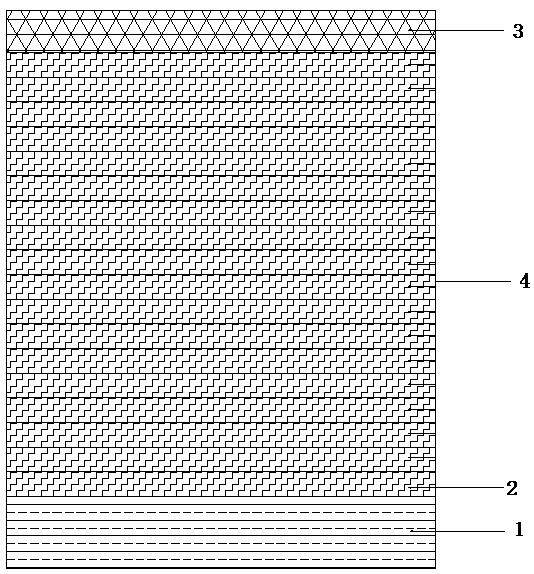
[0016] Embodiment 1, with reference to figure 1 , a layer structure for adjusting the thickness of the direct bonding area of ​​the trailing edge of the fan blade: in the area where the direct bonding thickness of the trailing edge of the blade is out of tolerance, several layers of glass fiber cloth 2 are pre-embedded on the PS surface and the SS surface of this area, The glass fiber cloth is laid on the lower surface of the inner skin layer 3 and the upper surface of the unidirectional cloth layer 1 on both the PS surface and the SS surface, and the gentle transition of the edges is maintained when laying, forming several layers of pre-embedded glass fiber cloth. Adjusting the structural layer 4, the adjusting structural layer 4 is integrally formed with the casing layer by means of vacuum infusion.

[0017] The glass fiber cloth laid on the adjustment structure layer 4 is a biaxial glass fiber cloth or a triaxial glass fiber cloth, and the laying direction is from the blade...

Embodiment 2

[0018] Embodiment 2, a method for adjusting the thickness of the direct bonding area of ​​the trailing edge of the fan blade, the steps are as follows:

[0019] (1) During the layering process of the shell, in the area where the direct bonding thickness of the trailing edge of the blade is out of tolerance, several layers of glass fiber cloth are pre-embedded on the PS and SS surfaces, and the glass fiber cloth is biaxial glass fiber cloth or triaxial To the glass fiber cloth, the laying direction is from the root of the blade to the tip of the blade;

[0020] (2) When the glass fiber cloth is laid, the starting point remains unchanged, and the end point is staggered layer by layer. The glass fiber cloth on the PS surface needs to be laid chordwise to fill the rear edge groove, and it is laid close to the rear edge parting line projection, and the glass fiber cloth on the SS surface is laid chordwise. The distance from the trailing edge parting line is 3-8mm. The glass fiber c...


PUM


Abstract

The invention discloses a draught fan blade rear edge direct bonding area thickness layer spreading structure. An area with the thickness super difference is directly bonded on the rear edges of blades, a plurality of layers of glass fabrics are embedded in each of the PS face and the SS face of the area, the glass fabrics on the PS face and the SS face are spread on the lower surface of an inner skin layer and the upper surface of a single-way fabric layer, during spreading, gentle transition of the edge is kept, and a plurality of adjusting structure layers formed through spreading of the glass fabrics which are embedded in advance are formed; the adjusting structure layers and a shell spreading layer are wholly molded in a vacuum infusion manner. The invention further discloses a draught fan blade rear edge direct bonding area thickness adjusting method. According to the structure and the method, the blade rear edge direct bonding area thickness super difference can be effectively removed, the strength of the blades is improved, the service life of the blades is prolonged, and the powerful guarantee is provided for the blade quality. The structure and the method are reasonable in design, easy to operate and obvious in effect.

Description

technical field [0001] The invention relates to the field of wind generator blade manufacturing, in particular to a thickness layer laying structure of the direct bonding area of ​​the trailing edge of the fan blade, and also relates to a method for adjusting the thickness of the direct bonding area of ​​the trailing edge of the wind power generator blade. Background technique [0002] Fan blades are one of the most critical components of wind turbines. As fan blades are getting longer and longer, the requirements for their quality and reliability are getting higher and higher. As a kind of composite material, fan blade has strong structural characteristics, and its mechanical properties and damage and failure laws not only depend on the properties of each component material, but also depend on the mesoscopic structural characteristics. The blade is usually mainly composed of suction side (SS) shell, pressure side (PS) shell and web parts, and the SS surface, PS surface and ...

Claims


Application Information

Patent Timeline
Patent Type & Authority Patents(China)
IPC IPC(8): B29C70/38
CPCB29C70/38
Inventor 陈露露林涛袁维瀚任拓张鑫
Owner GUODIAN UNITED POWER TECH LIANYUNGANG CO LTD
Learn More