Transmission belt forming hub

A technology for driving belts and forming surfaces, applied in belts, other household appliances, household appliances, etc., can solve problems such as leakage, difficulty in demoulding, affecting the production quality and production efficiency of rubber sleeves

Active Publication Date: 2016-12-07
GATES UNITTA POWER TRANSMISSION (SUZHOU) LIMITED
View PDF9 Cites 1 Cited by
  • Summary
  • Abstract
  • Description
  • Claims
  • Application Information

AI Technical Summary

Problems solved by technology

However, there are certain difficulties in detaching the unvulcanized rubber sleeve from the forming hub at present, refer to figure 1 , mainly because the current molding hub includes a skeleton 1, a molding surface 2 and a chamber 5 sealed between the skeleton and the molding surface, and the molding surface is provided with a plurality of air outlet holes 4 connected to the chamber. The air hole 3' feeds high-pressure gas into the chamber, and the high-pressure gas flows out through the air outlet on the forming surface after passing through the chamber, which facilitates the separation of the unvulcanized rubber sleeve from the molding surface, and the worker takes off the rubber sleeve. There is only one cavity, and the air holes on the forming surface are all connected to the cavity. For example, when the rubber sleeve is detached to the left, part of the air holes on the forming surface on the right side of the forming hub will be exposed, and the high-pressure gas will be released from the exposed air holes. A large amount of leakage in the middle causes insufficient air pressure in the chamber, resulting in the inseparability of the rubber sleeve on the left side of the forming hub from the surface of the forming hub, resulting in difficulty in demoulding, which seriously affects the production quality and production efficiency of the rubber sleeve.

Method used


Image

  • Transmission belt forming hub
  • Transmission belt forming hub
  • Transmission belt forming hub

Examples


Embodiment Construction

[0017] The present invention will be further described below through specific embodiments.

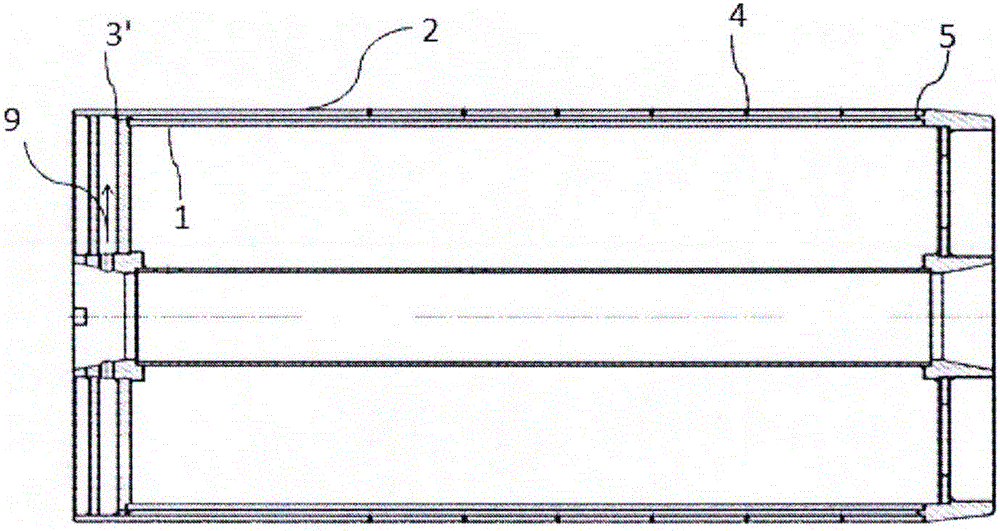
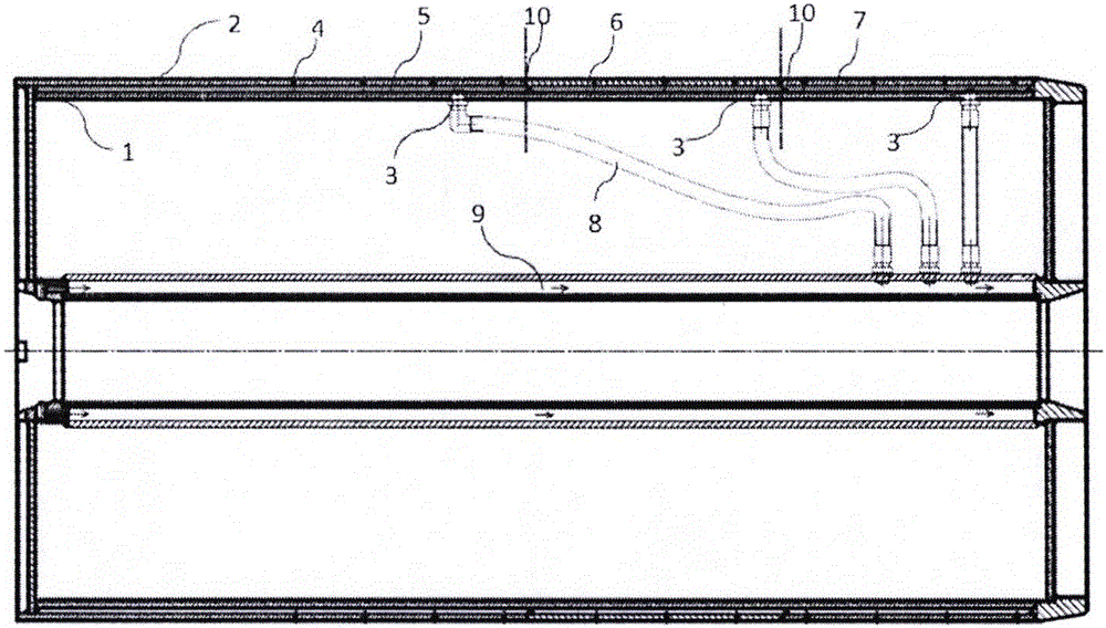
[0018] Such as figure 2 As shown, the transmission belt molding hub includes a skeleton 1, a molding surface 2, and a cavity formed between the skeleton and the molding surface by the outer wall of the chamber, the inner wall of the chamber, and the side wall of the chamber. There are several air holes on the surface 2, the inner wall of the chamber has air inlet holes, the outer wall of the chamber has air outlet holes, and the air outlet holes of the chamber and the corresponding air holes on the forming surface can communicate with each other. The skeleton includes a cylindrical outer wall. In this specific embodiment, the inner wall of the chamber is the outer wall of the skeleton, the outer wall of the chamber is the molding surface of the forming hub, and the side wall of the chamber can be the radial surface of the skeleton. Since the chamber is composed of the skeleton and Th...


PUM


Abstract

The invention provides a transmission belt forming hub. The hub comprises a framework, a forming surface and a chamber which is located between the framework and the forming surface and formed by an inner chamber wall, an outer chamber wall and a chamber side wall, wherein the chamber is connected with the framework and the forming surface; air holes are distributed in the forming surface; the chamber comprises at least two separated chamber bodies in the axial direction of the forming hub; and each chamber body comprises an air inlet and one or more air outlets communicating with the corresponding air holes in the forming surface. The novel forming hub can be separated from a rubber sleeve conveniently, and the quality of the rubber sleeve and the working efficiency are improved.

Description

Technical field: [0001] The invention belongs to the technical field of transmission belt production, and more specifically relates to the production of a forming hub for transmission belts. Background technique: [0002] The transmission belt forming hub is an important tool in the production process of the transmission belt. In the general transmission belt production, rubber, wire rope, cloth, etc. are wound on the transmission belt forming hub to form a rubber sleeve, and then the rubber sleeve is vulcanized and cut to form a transmission belt. Due to different production processes, some rubber sleeves need to be separated from the forming hub after being formed and put into the mold for vulcanization. Some rubber sleeves are directly carried on the forming hub for vulcanization, and then the vulcanized rubber sleeve is separated from the forming hub. Both are collectively referred to as demoulding. However, there are certain difficulties in detaching the unvulcanized r...

Claims


Application Information

Patent Timeline
IPC IPC(8): B29C41/26B29L29/00
CPCB29C41/26B29L2031/7092
Inventor 冯永强段让明陈贤义苏玉龙
Owner GATES UNITTA POWER TRANSMISSION (SUZHOU) LIMITED
Why Eureka
Try Eureka