
Longitudinal vibration motor

A longitudinal vibration and motor technology, applied in the direction of electromechanical devices, electrical components, etc., can solve the problems of asymmetrical upper and lower positions of the driving force, limiting the rapid response of the linear vibration motor, improving the vibration sense, and taking up a large space.

Active Publication Date: 2016-11-30
GOERTEK INC
View PDF7 Cites 9 Cited by
  • Summary
  • Abstract
  • Description
  • Claims
  • Application Information

AI Technical Summary

Problems solved by technology

Traditional longitudinal vibration motors are mostly cylindrical in shape, and due to the limitation of structural features, they occupy a large space
In its internal structure, the moving magnet type is ideal, but when it vibrates upwards, the permanent magnet tends to deviate far from the area where the coil magnetic field acts, and the Lorentz force received is significantly reduced, and the driving force is asymmetrical at the upper and lower positions, resulting in driving efficiency. Low
Limits the quick response and vibration enhancement of the linear vibration motor

Method used


Image

  • Longitudinal vibration motor
  • Longitudinal vibration motor
  • Longitudinal vibration motor

Examples


Embodiment Construction

[0034] Various exemplary embodiments of the present invention will now be described in detail with reference to the accompanying drawings. It should be noted that the relative arrangements of components and steps, numerical expressions and numerical values ​​set forth in these embodiments do not limit the scope of the present invention unless specifically stated otherwise.

[0035] The following description of at least one exemplary embodiment is merely illustrative in nature and in no way taken as limiting the invention, its application or uses.

[0036] Techniques, methods and devices known to those of ordinary skill in the relevant art may not be discussed in detail, but where appropriate, such techniques, methods and devices should be considered part of the description.

[0037] In all examples shown and discussed herein, any specific values ​​should be construed as exemplary only, and not as limitations. Therefore, other instances of the exemplary embodiment may have dif...


PUM


Abstract

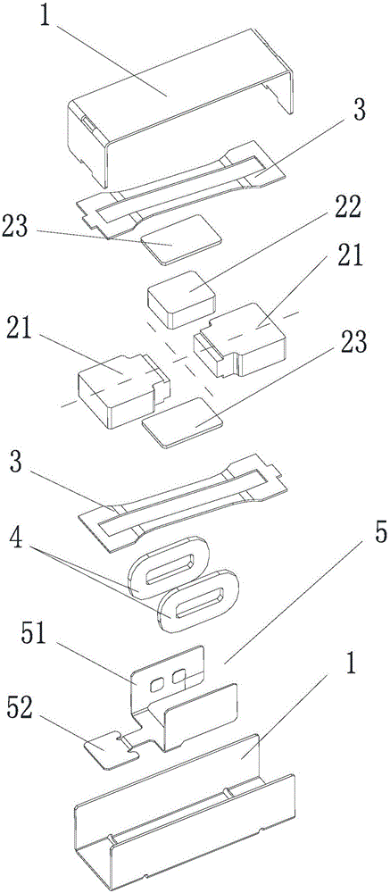
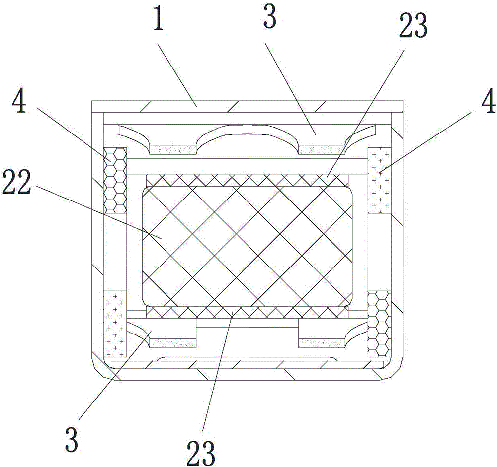
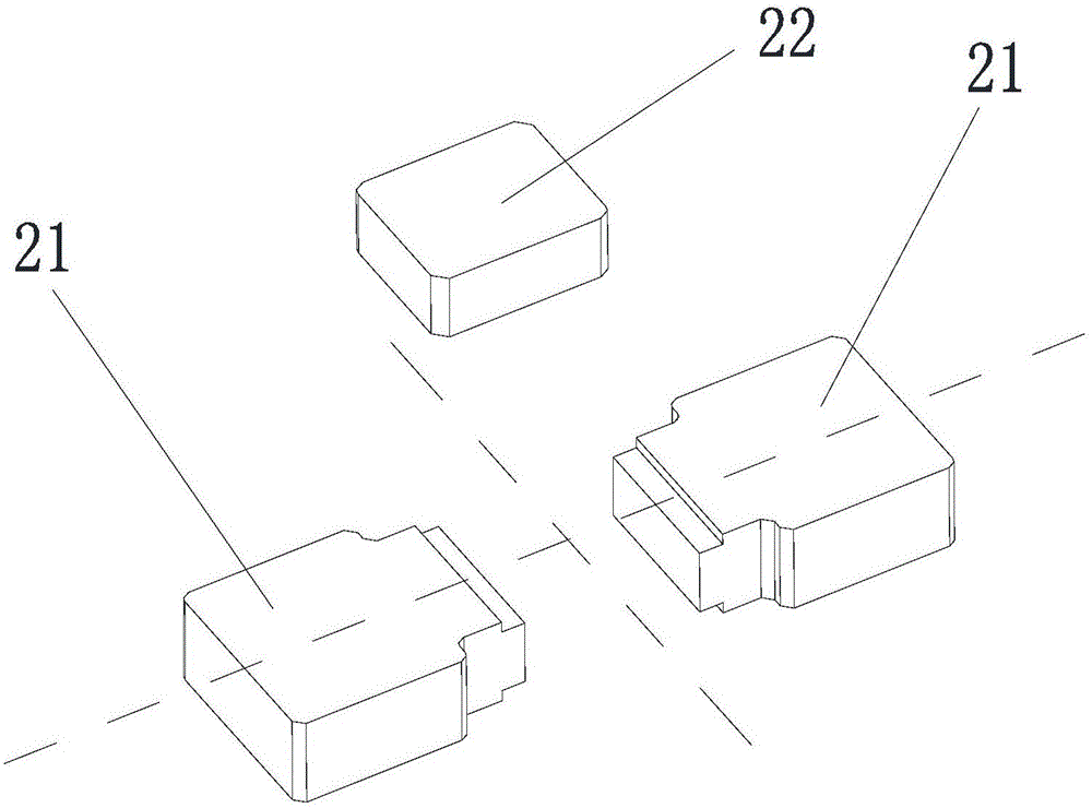
The invention discloses a longitudinal vibration motor. The longitudinal vibration motor comprises a shell, a vibration block assembly, elastic sheet assemblies, a coil and an external circuit, wherein the shell is internally provided with a containing cavity; the vibration block assembly is arranged in the containing cavity, and comprises a mass block and a magnet which is fixedly on the mass block; the magnetic pole of the magnet is longitudinally distributed; the elastic sheet assemblies are arranged on the upper side and lower side of the vibration block assembly, and are configured to suspend the vibration block assembly in the containing cavity; the coil is arranged at a side position of the magnet; when the vibration block assembly is located at a balance position, the coil is dead against the magnet and the upper and lower edges of the magnet correspond to a coil cylinder section position of the coil; and the external circuit is electrically connected with the coil and is configured to be electrically connected with external equipment.

Description

technical field [0001] The invention belongs to the technical field of electronic products, in particular, the invention relates to a longitudinal vibration motor. Background technique [0002] With the gradual development of electronic product technology, vibration motors have become commonly used functional devices in electronic products such as mobile phones and tablet computers. Existing miniature vibrating motors usually include a vibration assembly and a stator assembly. The vibration assembly is composed of a mass block, a permanent magnet and a shrapnel, and the stator assembly is composed of an FPCB, a damper, a limit block and a coil. In order to make the vibrating component vibrate back and forth, electromagnetic interaction needs to be generated between the coil and the magnet, and the change of the current in the coil causes the magnetic field to change, so that the vibrating component moves. [0003] Among existing miniature vibration motors, longitudinal vibr...

Claims


Application Information

Patent Timeline
Patent Type & Authority Applications(China)
IPC IPC(8): H02K33/02
CPCH02K33/02
Inventor 刘春发朱跃光臧伟晔
Owner GOERTEK INC
Learn More