Pressure-sensor chip
A pressure sensor, sensor technology, applied in the direction of measuring fluid pressure, instruments, pressure difference measurement between multiple valves, etc., to prevent concentration, eliminate poor action, and ensure pressure resistance.
- Summary
- Abstract
- Description
- Claims
- Application Information
AI Technical Summary
Problems solved by technology
Method used
Image
Examples
Embodiment approach 1
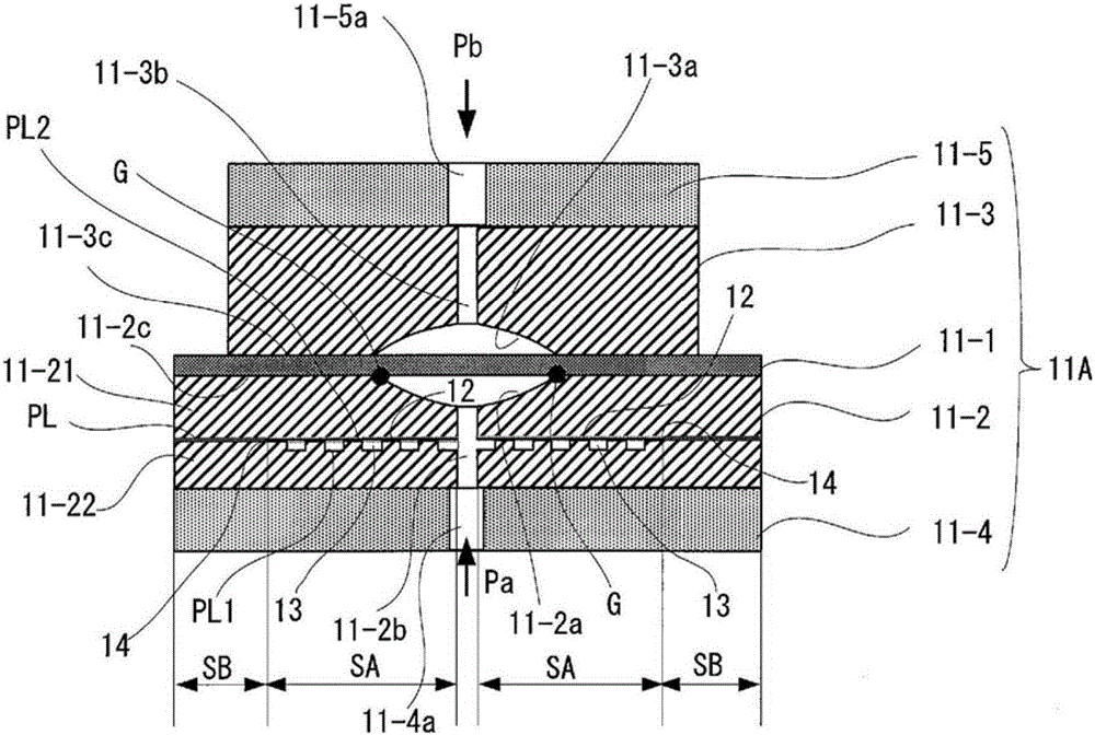
[0054] figure 1 It is a diagram showing the outline of the first embodiment (Embodiment 1) of the pressure sensor chip of the present invention.
[0055] exist figure 1 In the pressure sensor chip 11A shown, 11-1 is a sensor diaphragm, 11-2 and 11-3 are first and second stopper members as holding members bonded via the sensor diaphragm 11-1, 11-4 and 11-5 is the 1st and 2nd pedestal which joins with the stopper member 11-2 and 11-3. The blocking members 11-2, 11-3, and the pedestals 11-4, 11-5 are made of silicon, glass, or the like.
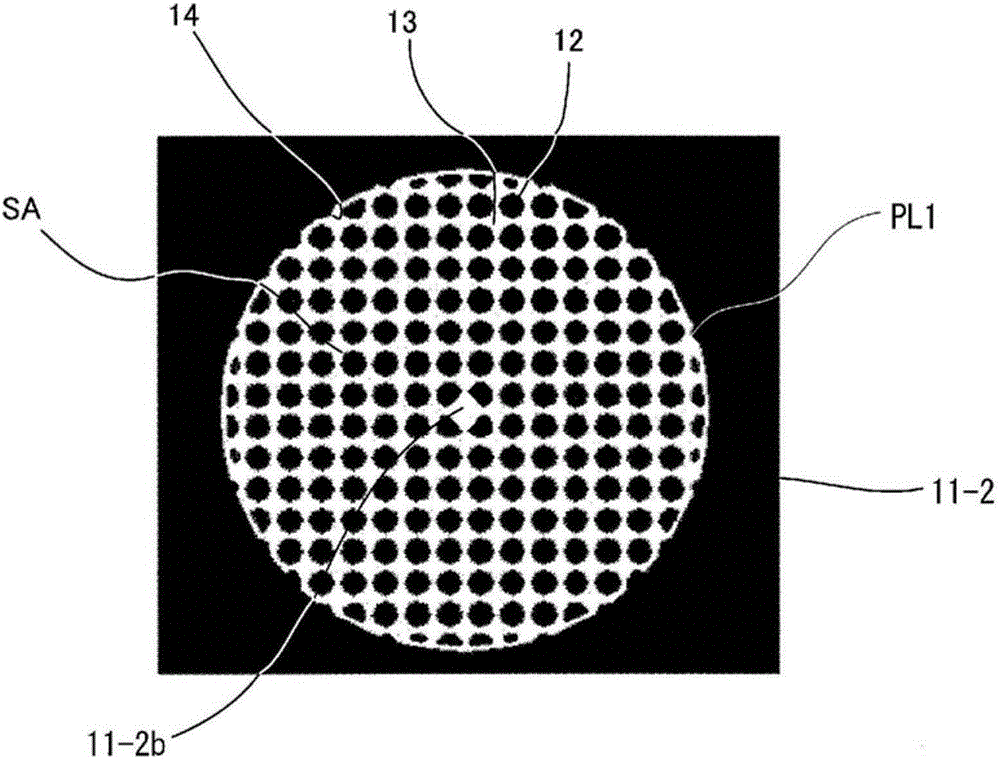
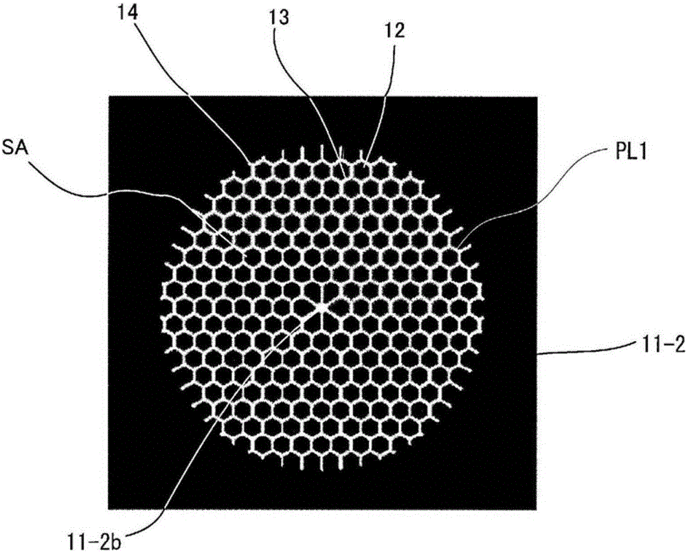
[0056] In this pressure sensor chip 11A, recesses 11-2a, 11-3a are formed in the stopper members 11-2, 11-3, and the recesses 11-2a of the stopper member 11-2 face one side of the sensor diaphragm 11-1. , the concave portion 11-3a of the blocking member 11-3 faces the other face of the sensor diaphragm 11-1. The recesses 11-2a, 11-3a are curved surfaces (aspherical surfaces) along the displacement of the sensor diaphragm 11-1, and pressure...
Embodiment approach 2
[0070] Figure 7 The outline of the second embodiment (Embodiment 2) of the pressure sensor chip of the present invention is shown in . In the pressure sensor chip 11B of the second embodiment, the annular groove 11-2 is formed in the stopper member 11-2 and is continuous with the non-joining area SA and dug in the wall thickness direction of the stopper member 11-3. 2d. As a result, the groove 11-2d is formed so as to protrude in the wall thickness direction of the blocking member 11-3. It is desirable that the ring-shaped groove 11-2d is not a discretely segmented groove but a continuous groove to increase the diameter of the groove section.
[0071] In addition, in Figure 7 In the illustrated example, the cross-sectional shape of the annular groove 11-2d perpendicular to the non-joining area SA is circular, but it may not necessarily be circular, for example, as Figure 8 As shown, it may be slit-shaped (rectangular) or the like.
[0072] Figure 9 In the pressure se...
Embodiment approach 3
[0074] Figure 10 The outline of the third embodiment (Embodiment 3) of the pressure sensor chip of the present invention is shown in . Like the pressure sensor chip 11B of the second embodiment, the pressure sensor chip 11C of the third embodiment includes a non-joining area SA and an annular groove 11-2d continuous with the non-joining area SA inside the barrier member 11-2. , but differs from the pressure sensor chip 11B of Embodiment 2 in the following points.
[0075] In this pressure sensor chip 11C, a region S1 facing one side of the sensor diaphragm 11-1 in the peripheral portion 11-2c of the barrier member 11-2 includes a region S1a on the outer peripheral side and a region S1b on the inner peripheral side. The region S1a on the outer peripheral side is a bonding region to one surface of the sensor diaphragm 11-1, and the region S1b on the inner peripheral side is a non-bonding region to one surface of the sensor diaphragm 11-1.
[0076] In addition, a region S2 fac...
PUM
 Abstract
Description
Claims
Application Information
 - Generate Ideas
- Intellectual Property
- Life Sciences
- Materials
- Tech Scout
- Unparalleled Data Quality
- Higher Quality Content
- 60% Fewer Hallucinations
Browse by: Latest US Patents, China's latest patents, Technical Efficacy Thesaurus, Application Domain, Technology Topic, Popular Technical Reports.
© 2025 PatSnap. All rights reserved.Legal|Privacy policy|Modern Slavery Act Transparency Statement|Sitemap|About US| Contact US: help@patsnap.com


