
Machine vision assisted laser three-dimensional scanning and marking method

A laser three-dimensional and machine vision technology, applied in the direction of instruments, optical devices, measuring devices, etc., to achieve the effect of simple calibration steps, convenient marking and operation, and ensuring accuracy and reliability

Active Publication Date: 2016-11-23
NANJING UNIV OF AERONAUTICS & ASTRONAUTICS
View PDF3 Cites 18 Cited by
  • Summary
  • Abstract
  • Description
  • Claims
  • Application Information

AI Technical Summary

Problems solved by technology

[0003] The purpose of the present invention is to provide a laser three-dimensional scanning marking method assisted by machine vision, which can effectively solve the problem of marking complex target contour curves on complex three-dimensional curved surfaces

Method used


Image

  • Machine vision assisted laser three-dimensional scanning and marking method
  • Machine vision assisted laser three-dimensional scanning and marking method
  • Machine vision assisted laser three-dimensional scanning and marking method

Examples


Embodiment Construction

[0018] In order to facilitate the understanding of those skilled in the art, the present invention will be further described below in conjunction with the embodiments and accompanying drawings, and the contents mentioned in the embodiments are not intended to limit the present invention.

[0019] The laser three-dimensional scanning marking method assisted by machine vision proposed by the present invention only needs the digital model of the marked three-dimensional curved surface w M and k (k≥n) visual feature points whose spatial position is known and whose relative position relationship with the three-dimensional surface is known.

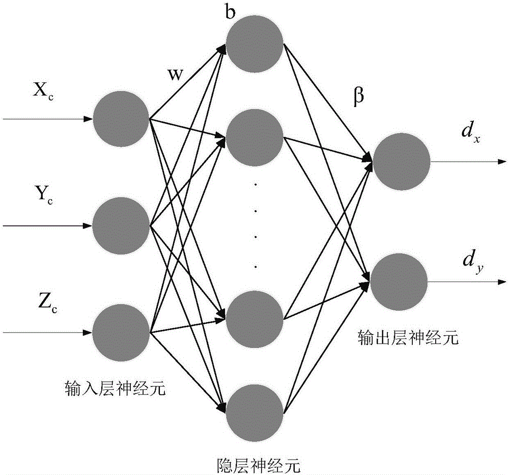
[0020] refer to figure 1 As shown, the laser three-dimensional scanning marking method assisted by machine vision of the present invention is based on a marking system, which includes: an industrial camera whose imaging parameters have been calibrated, a laser scanning vibrating mirror and a computer; the laser scanning vibrating mirror include...


PUM


Abstract

The invention discloses a machine vision assisted laser three-dimensional scanning and marking method, comprising: distributing visual characteristic points with known spatial positions and known relative positional relation with a three-dimensional surface, acquiring images of the visual characteristic points by the aid of a calibrated industrial camera, and determining a spatial pose relation between the three-dimensional surface and the camera by using prospective-n-point theory; entering digital control signals to a marking system to form laser spots covering the three-dimensional surface, using the camera to acquire images of the laser spots, and accordingly constructing a mapping relation between laser scanning galvanometer digital control signals and three-dimensional point coordinates on the surface in a camera coordinate system; using the constructed mapping relation to solve digital control signals corresponding to the discrete three-dimensional points on a target outline curve so as to control a laser galvanometer to mark out the target outline curve on the three-dimensional surface. Field real-time calibration ensures precision and reliability of each single use, and the whole marking operation is convenient.

Description

technical field [0001] The invention belongs to the technical field of positioning on a three-dimensional curved surface, and specifically refers to a method for marking a target contour curve on a three-dimensional curved surface by mainly using a laser scanning galvanometer and an industrial camera. Background technique [0002] With the continuous development of science and technology and industrial production, there is an increasing demand to mark the processing area on the three-dimensional surface to assist in the completion of production operations. For example, composite material layup in the aviation field needs to be marked on the three-dimensional surface The laying position and shape of composite materials are used to complete the laying of composite materials; the spraying of trademarks or product appearance patterns also needs to mark the spraying position and shape on the three-dimensional curved surface to assist spraying. At present, the existing method firs...

Claims


Application Information

Patent Timeline
Patent Type & Authority Applications(China)
IPC IPC(8): G01B11/24
CPCG01B11/24
Inventor 王敏刚涂俊超张丽艳
Owner NANJING UNIV OF AERONAUTICS & ASTRONAUTICS
Learn More