Low-pressure large-flow water saving mechanism

A flow regulator and flow channel technology, applied in mechanical equipment, water supply devices, engine components, etc., can solve the problems of limited throttling effect and small flow rate.

Active Publication Date: 2016-11-23
XIAMEN SOLEX HIGH TECH IND CO LTD
View PDF9 Cites 4 Cited by
  • Summary
  • Abstract
  • Description
  • Claims
  • Application Information

AI Technical Summary

Problems solved by technology

The above-mentioned water-saving mechanism has limited...

Method used


Image

  • Low-pressure large-flow water saving mechanism
  • Low-pressure large-flow water saving mechanism
  • Low-pressure large-flow water saving mechanism

Examples


Embodiment 1

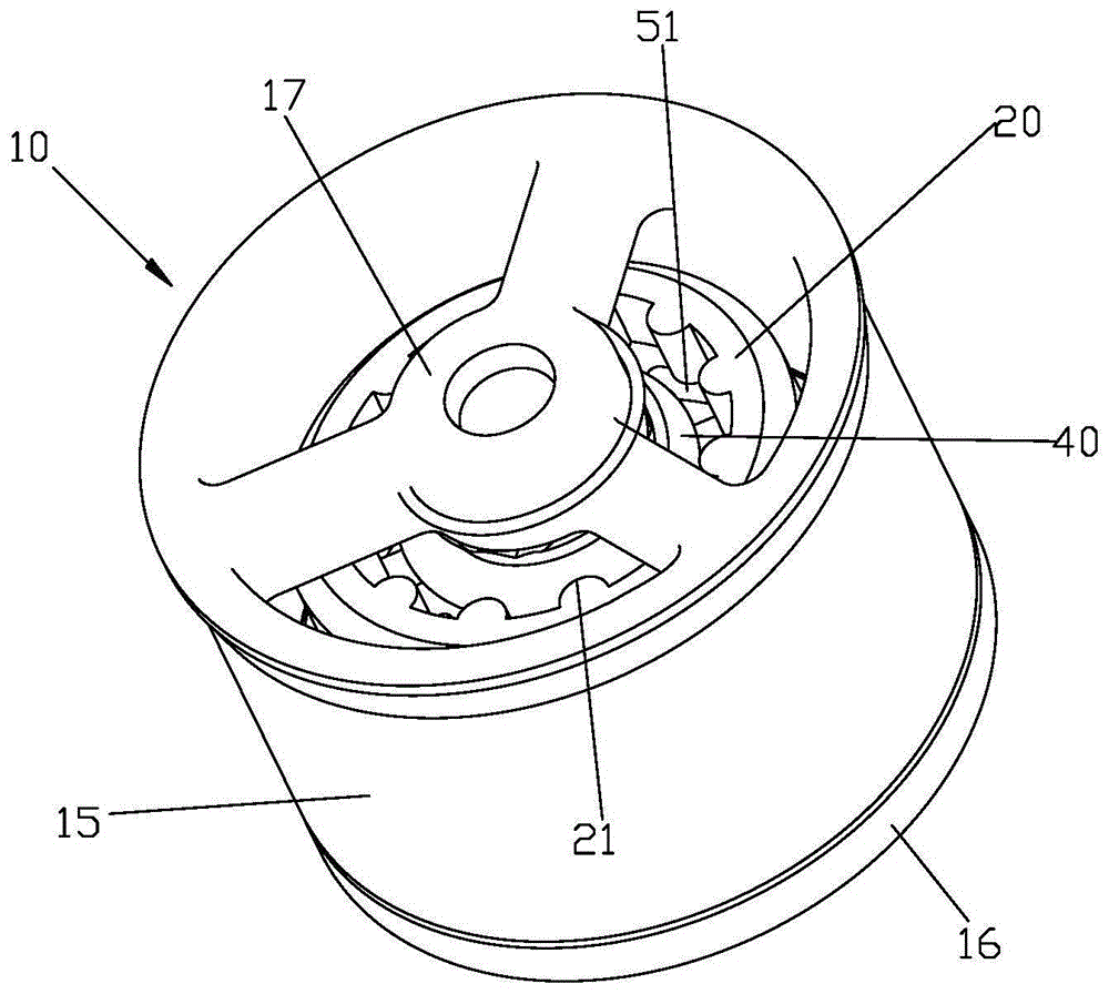
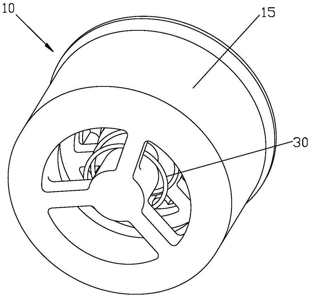
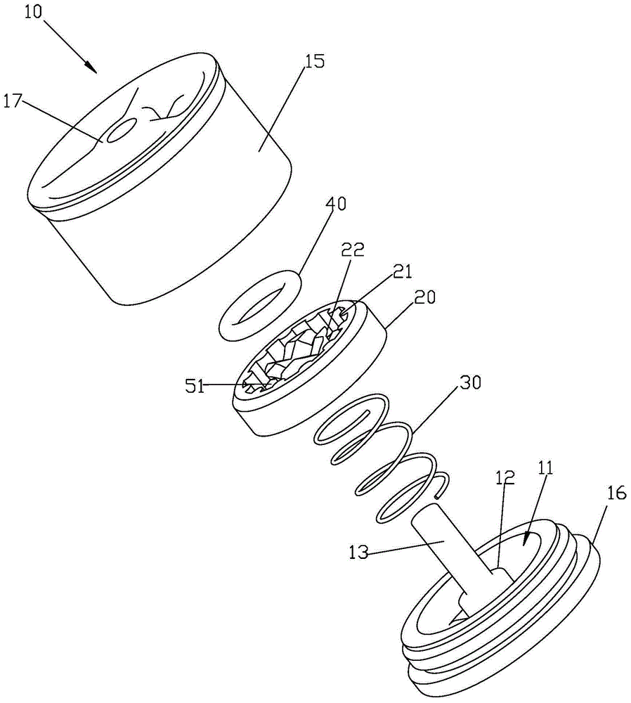
[0048] Please check Figure 1 to Figure 9 , The low-pressure and high-flow water-saving mechanism includes a solid seat 10 , a flow regulator 20 , an elastic body 30 and at least one bypass channel 52 . The flow regulator 20 has a normally open channel 51 ; the at least one bypass channel 52 is formed outside the flow regulator 20 , and the bypass channel 52 is independent from the normally open channel 51 .

[0049] The fixing seat 10 is provided with a penetrating installation space 11, and the inner wall of the installation space 11 includes a large hole wall, a small hole wall and a stepped surface connecting the large hole wall and the small hole wall. The fixed seat 10 includes a middle seat 12 located in the installation space 11, the middle seat 12 is fixed in the installation space 11 through the third spoke, and a guide column 13 is fixedly arranged on the middle seat 12.

[0050] The flow regulator 20 includes an elastically deformable throttle portion 40 .

[005...

Embodiment 2

[0059] Please check Figure 10 , it is different from Embodiment 1 in that: the diameter of the small hole wall is equal to the outer diameter of the flow regulator 20, the second position is not higher than the step surface, the top surface of the middle seat is lower than the step surface, and the flow regulator 20 is sealed and slippery. At the wall of the small hole, the bypass channel is in a closed state, and the restricting flow regulator 20 is in the second position through the top surface of the middle seat, and the restricting flow regulator 20 is in the second position.

Embodiment 3

[0061] Please check Figure 11 , it differs from Embodiment 1 in that: the fixed seat 10 is also provided with a through hole 53 that penetrates the installation space 11 inside and outside, and the inner port of the through hole 53 is located on the wall of the large hole, and the through hole also constitutes the waterway of the water saving mechanism. part.


PUM


Abstract

The invention discloses a large-pressure high-flow water saving mechanism. The low-pressure large-flow water saving mechanism comprises a flow adjuster (20) and at least one bypass channel (52), wherein the flow adjuster (20) is provided with a normally open flow channel (51), and each bypass channel (52) is formed inside or outside the flow adjuster (20) and independent of the normally open flow channel (51). The flow adjuster (20) overcomes a reset force under the water flow pressure to slide between at least a first position and a second position. When the flow adjuster (20) is located at the first position, the flow area of each bypass channel (52) is larger than the flow area, existing when the flow adjuster (20) is located at the second position, of the bypass channel (52). The low-pressure high-flow water saving mechanism has the advantages that the normally open flow channel and the bypass channels are arranged, the normally open flow channel is normally open, when the flow adjuster is located at the first position, the flow area of each bypass channel is larger than the flow area, existing when the flow adjuster is located at the second position, of the bypass channel, the flow adjuster overcomes the reset force under the water flow pressure to slide between the first position and the second position, and therefore when the pressure is low, the bypass channels are opened, so a low-pressure large flow can be achieved.

Description

technical field [0001] The invention relates to a low-pressure and high-flow water-saving mechanism. Background technique [0002] Now the water-saving mechanism includes a fixed seat and a throttling part, the fixed seat is provided with a penetrating installation space, and the throttling part is fixed in the installation space of the fixed seat. Use the combination of the throttling part and the installation space to use the deformation characteristics of the water pressure to change the water passing area of ​​the installation space to achieve throttling. The change in area is small, the water passing area of ​​the shielding installation space is small, and the flow rate is large; when the water pressure is high, the throttling part is deformed by the water pressure, the water passing area of ​​the installation space changes greatly, and the water passing area of ​​the shielding installation space is large. The flow rate is small; or, the throttling part is provided wit...

Claims


Application Information

Patent Timeline
IPC IPC(8): F16K17/30
CPCE03C1/08
Inventor 吴石龙赵国松邱月华
Owner XIAMEN SOLEX HIGH TECH IND CO LTD
Why Eureka
Try Eureka