
Overhead building machine

A space and main technology, applied in the field of aerial building machines, can solve the problems of difficult pre-control of construction cycle, complicated and troublesome production process, and affecting the accuracy of upper-level units.

Active Publication Date: 2016-11-23
SHENZHEN EXCELLENCE INDZATION INTELLIGENT CONSTR DEV CO LTD
View PDF9 Cites 10 Cited by
  • Summary
  • Abstract
  • Description
  • Claims
  • Application Information

AI Technical Summary

Problems solved by technology

Although this method can optimize resource allocation to a certain extent, reduce resource consumption, and improve the engineering quality, functional quality, environmental quality and construction labor productivity level of the house, it has the following disadvantages: 1. The production cost is high, and the production cost is high. The process is complicated and troublesome; 2. Inconvenient transportation and stacking; 3. There are gaps between two adjacent prefabricated panels, which may easily lead to water leakage; 4. It is necessary to train a large number of workers, the cost of workers is large, and the construction cost is difficult to control. It is difficult to predict the quality of the project and the construction period. In this way, for today's high labor cost and labor shortage, it is undoubtedly not conducive to the sustainable development of construction enterprises.
However, in the above-mentioned technical scheme, the main mold used to form the wall structure does not run very smoothly when it rises after completing the floor of a unit; when the building floor is getting higher and higher, shaking will occur, which greatly affects the The precision when constructing the upper unit will have a certain impact on the quality of the house if it is not handled properly

Method used


Image

  • Overhead building machine
  • Overhead building machine
  • Overhead building machine

Examples


Embodiment Construction

[0160] In order to fully understand the technical content of the present invention, the technical solutions of the present invention will be further introduced and illustrated below in conjunction with specific examples, but not limited thereto.

[0161] The aerial building machine provided by the present invention is suitable for high-rise and super high-rise residential buildings, and this case mainly takes the super-high-rise affordable housing with a building height of 80m to 180m and a floor height of 2.8m as the object of description, but its implementation is not based on this limit.

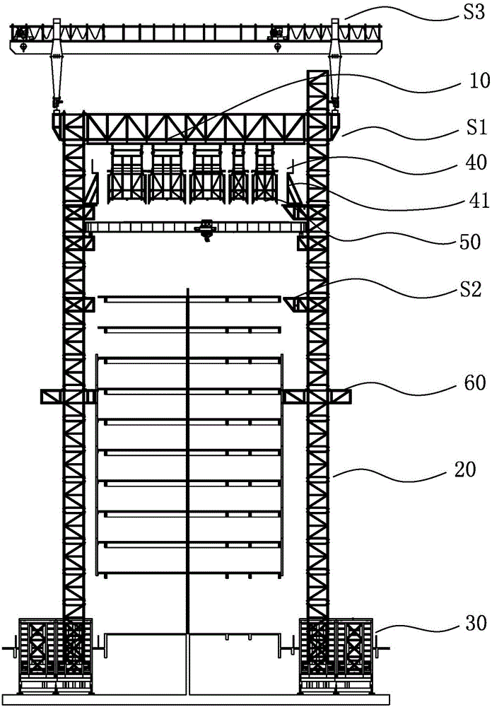
[0162] Such as figure 1 As shown, the aerial building machine includes: a main space lifting platform S1 for building residential walls, a floor construction platform S2 for pouring floor concrete, installing wall beam steel mesh and installing exterior wall insulation panels, and a gantry crane. S3, and the control system (not shown in the figure); the floor construction platform S2, is...


PUM


Abstract

The invention relates to an overhead building machine, and belongs to the technical field of building equipment. The overhead building machine comprises a main body space lifting platform, a floor construction platform, a gantry crane and a control system. The main body space lifting platform comprises a main body steel frame platform, a main body lifting column, a lifting driving unit, a formwork frame, a concrete conveying device, a concrete distribution machine and a spraying device. Due to the fact that the lifting driving unit is adopted and a stability maintaining supporting frame is arranged on the outer formwork frame, the operation of the whole overhead building machine is smoother and more stable. The gantry crane is adopted for carrying all the components of the building machine, so that the building machine is safer and more convenient to assemble and disassemble; an automatic formwork opening and closing mechanism is adopted for opening and closing the formwork frame, so that the formwork frame opening and closing speed is increased; a transition connection device is arranged between the main body steel frame platform and the formwork frame, so that the strength of the formwork frame is enhanced, and the service life of the formwork frame is prolonged.

Description

technical field [0001] The invention relates to an aerial building machine suitable for high-rise and super high-rise residential buildings, belonging to the technical field of construction equipment. Background technique [0002] There are many large cities and megacities in China, but construction land resources are scarce. Not only in first- and second-tier cities, but also in third- and fourth-tier cities, most of the residences appear in the form of high-rise buildings. [0003] In China, the classification of civil buildings according to the number of floors above the ground or the height shall comply with the following regulations: [0004] 1. Residential buildings are classified according to the number of floors: the first to third floors are low-rise residential buildings, the fourth to sixth floors are multi-storey residential buildings, the seventh to ninth storeys are middle and high-rise residential buildings, and the tenth and above tenth floors are high-rise ...

Claims


Application Information

Patent Timeline
IPC IPC(8): E04G11/28E04G21/00E04G21/04E04G21/16E04G21/24
CPCE04G11/28E04G21/00E04G21/0427E04G21/16E04G21/246
Inventor 董善白
Owner SHENZHEN EXCELLENCE INDZATION INTELLIGENT CONSTR DEV CO LTD
Learn More