
Method for detecting integrity of hole wall rock mass of large-diameter cast-in-place pile during pile foundation construction period of cast-in-place pile

A detection method and technology of cast-in-situ piles, which are applied in the direction of foundation structure engineering, foundation structure test, construction, etc., can solve problems such as different elastic wave parameters, different elastic wave types, and different detection environments, so as to achieve small impact and reduce construction costs. Difficulty, the effect of speeding up the construction progress

Active Publication Date: 2016-11-23
ARCHITECTURAL DESIGN RES INST OF GUANGDONG PROVINCE +1
View PDF5 Cites 7 Cited by
  • Summary
  • Abstract
  • Description
  • Claims
  • Application Information

AI Technical Summary

Problems solved by technology

[0009] 2. The detection environment is different
[0012] 2. The detection environment is different
[0013] 3. Different types of elastic waves for detection applications
[0014] 4. The elastic wave parameters used for judgment and interpretation are different
The Chinese patent with the application number ZL200310112325.0 is only used to determine the properties of the rock and soil next to the drilling hole;
[0017] 2. The detection environment is different
[0018] 3. The timing of detection is different

Method used


Image

  • Method for detecting integrity of hole wall rock mass of large-diameter cast-in-place pile during pile foundation construction period of cast-in-place pile
  • Method for detecting integrity of hole wall rock mass of large-diameter cast-in-place pile during pile foundation construction period of cast-in-place pile
  • Method for detecting integrity of hole wall rock mass of large-diameter cast-in-place pile during pile foundation construction period of cast-in-place pile

Examples


Embodiment Construction

[0072] The method for detecting the integrity of the large-diameter cast-in-place pile hole wall rock mass synchronously during the construction of the cast-in-place pile foundation of the present invention was once applied to a certain project of Guangzhou Baiyun International Airport. Drilling found that the karst in this area is strongly developed.

[0073] According to the current technical specification, the depth of the final hole must be no less than 4m for the full section of the pile foundation to enter the complete rock mass. Based on this, the designer has given the estimated final hole depth for each pile position, which is generally deep. Some piles contact the bedrock from about 20m, and need to be as deep as 80m to meet the specification requirements of no less than 4m for the full section to enter the complete rock mass.

[0074] During the construction process, it was found that there were multi-layered karst caves, and although the cumulative thickness of th...


PUM


Abstract

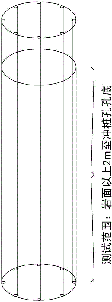
The invention discloses a method for detecting integrity of hole wall rock mass of a large-diameter cast-in-place pile during a pile foundation construction period of the cast-in-place pile. The method comprises the following steps: (1) arranging a plurality of detecting fracture surfaces, in the axial direction of a pile hole, on the inner wall of the pile hole after the pile hole of the cast-in-place pile is completed and before concrete is poured during the pile foundation construction period of the large-diameter cast-in-place pile in a karst region; (2) adopting an acoustic well logging equipment; (3) starting detection after an emitting probe and a receiving probe are stable, and storing detected results by adopting a time section oscillogram; (4) analyzing the time section oscillogram obtained in step (3), and dividing intact rock mass, a soil layer and karst; and (5) after all to-be-detected fracture sections are detected, calculating complete rock wall area of the whole pile hole wall, and providing basis for calculating pile foundation pulling resistance and pile side frictional resistance of the cast-in-place pile. The detecting method is quick and accurate, can greatly shorten the construction period, can reduce manpower and material resources, and can reduce construction difficulty and construction risk of the pile foundation.

Description

technical field [0001] The invention relates to a method for detecting the hole wall rock mass of cast-in-situ piles in construction engineering, in particular to a method for detecting the integrity of the hole wall rock mass of large-diameter cast-in-place piles which is carried out synchronously during the construction of the cast-in-place pile foundation. Background technique [0002] The area of ​​the complete bedrock around the pile is one of the necessary basis for the calculation of the pullout force and pile side friction resistance of the large-diameter cast-in-place pile. The area of ​​the complete bedrock around the pile is equal to the product of the length of the pile entering the complete bedrock and the circumference of the pile. . [0003] At present, the pile foundation pullout force and pile side friction resistance of large-diameter cast-in-situ piles are mainly estimated based on the results of advanced drilling. Due to the limited number of advanced dr...

Claims


Application Information

Patent Timeline
Patent Type & Authority Applications(China)
IPC IPC(8): E02D33/00
CPCE02D33/00
Inventor 陈星李学文区彤章哲辉刘雪兵彭超林泳马锦国谢汉阳孙义邓杰方
Owner ARCHITECTURAL DESIGN RES INST OF GUANGDONG PROVINCE
Learn More