
Automatic mechanical frame lifting device

An automatic lifting and mechanical technology, applied in the direction of lifting devices, etc., can solve the problems of environmental pollution around the oil, and achieve the effects of uniform force, improved stability, and high precision

Active Publication Date: 2016-11-23
XIAN SKYHAWK DEFENSE TECH CO LTD
View PDF6 Cites 8 Cited by
  • Summary
  • Abstract
  • Description
  • Claims
  • Application Information

AI Technical Summary

Problems solved by technology

[0003] The purpose of the present invention is to overcome the defects of the existing lifting device, to provide a pollution-free, mechanical frame automatic lifting device that can lift precisely, and through a reasonable structural design, it solves the problem of oil in the lifting of the hydraulic cylinder. The problem of liquid pollution to the surrounding environment, at the same time the invention achieves precise lifting

Method used


Image

  • Automatic mechanical frame lifting device
  • Automatic mechanical frame lifting device

Examples


Embodiment Construction

[0024] The present invention will be further described below in conjunction with the accompanying drawings, but the protection scope of the present invention is not limited thereto.

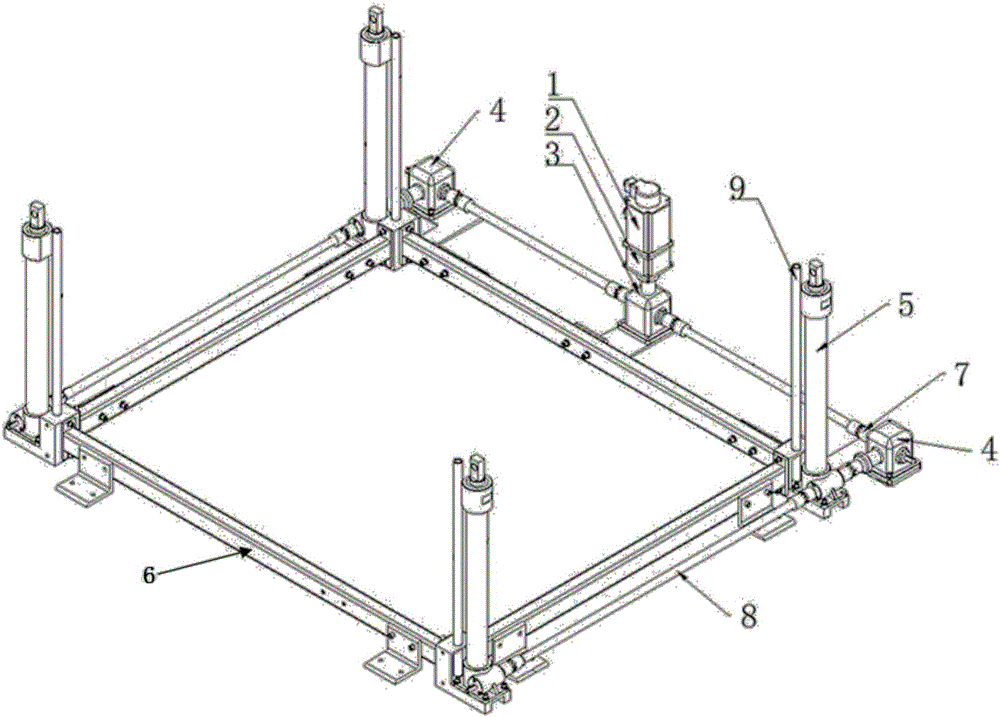
[0025] Such as figure 1 As shown, the present invention includes a support frame 6, a plurality of lifting cylinders 5 with the same height arranged on the support frame 6 and a power system. In this embodiment, two groups of lifting cylinders 5 are arranged on the support frame 6, each Each group includes two lift cylinders 5, and the support frame 6 is designed as a rectangular structure. The four lift cylinders 5 are arranged in pairs on the two parallel sides of the rectangular support frame 6, and the support frame 6 is also provided with There is a guide rod 9 parallel to the lift cylinder 5, and the top of the guide rod 9 is fixedly connected to the top of the lift cylinder 5, which can effectively stabilize the lifting direction of the lift cylinder 5;

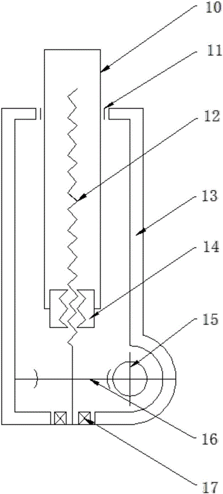
[0026] Such as figure 2 As show...


PUM


Abstract

The invention discloses an automatic mechanical frame lifting device. The automatic mechanical frame lifting device comprises a support frame and lifting cylinders arranged on the support frame, wherein each lifting cylinder comprises a cylinder body and a screw shaft vertically arranged in the cylinder body; a bearing seat used for supporting and fixing the screw shaft is arranged at the bottom of the cylinder body; a lifting rod with the interior as a cavity is also arranged in the cylinder body; a nut is arranged at the bottom of the lifting rod; the screw shaft penetrates through the nut and stretches into the inner cavity of the lifting rod; the lifting rod rises and falls along with rotation of the screw shaft; an opening is formed in the top of the cylinder body; the upper end of the lifting rod stretches out of the cylinder body via the opening. Through the automatic mechanical frame lifting device, a mechanical lifting cylinder structure is used for replacing a hydraulic oil cylinder as power; the pollution to the environment is avoided; meanwhile, through the lifting cylinder adopting the structure, the screw shaft drives the lifting cylinder to move up and down; the accuracy of the lifting height is consistent with the accuracy of the screw shaft; a servo motor is used for controlling revolutions of the screw shaft to reach corresponding lifting height.

Description

technical field [0001] The invention relates to the technical field of mechanical auxiliary lifting devices, in particular to a mechanical frame automatic lifting device. Background technique [0002] Existing lifting devices are mostly used in the process of overhauling and maintaining equipment to lift the equipment according to specific needs. At present, the most widely used ones are automobiles and engineering equipment. The lifting device can be divided into mechanical type, hydraulic type and pneumatic type according to different power sources; it can be divided into single-column type, double-column type, four-column type and shear type according to different structures; the popular four-column type is hydraulic drive, They all use hydraulic cylinders as the lifting power output. The problem of poor sealing is easy to occur, and the hydraulic oil is easy to leak, polluting the surrounding environment. Contents of the invention [0003] The purpose of the present ...

Claims


Application Information

Patent Timeline
IPC IPC(8): B66F11/00B66F3/18
CPCB66F3/18B66F3/44B66F3/46B66F11/00
Inventor 吴虎胜周振宇
Owner XIAN SKYHAWK DEFENSE TECH CO LTD
Learn More