
Ventilation hood

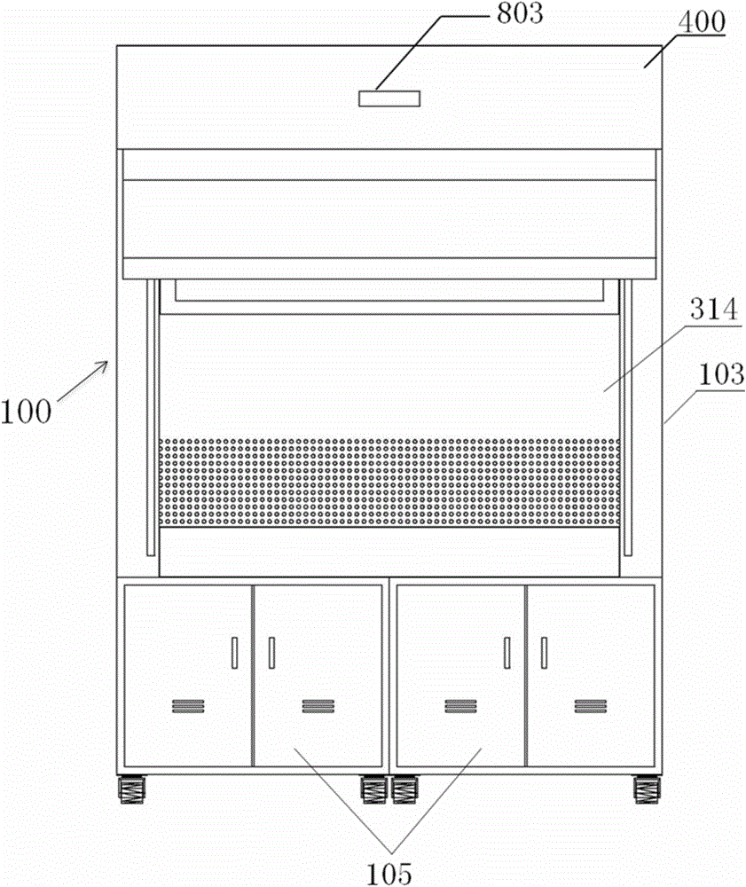
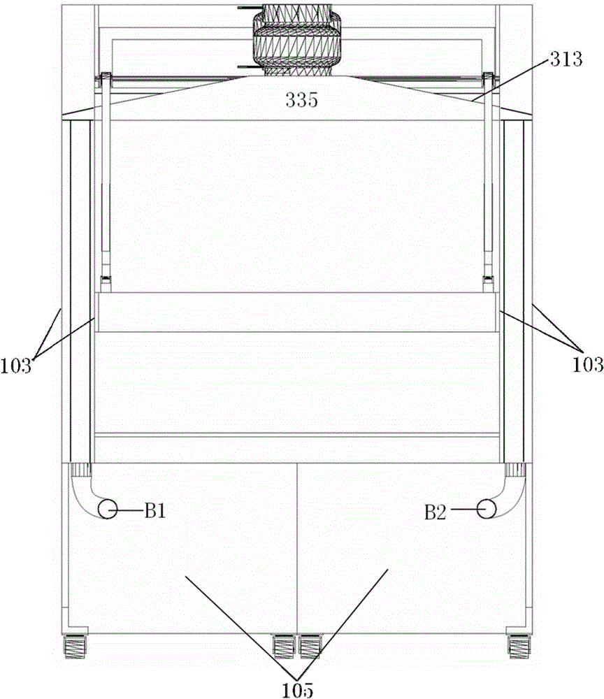
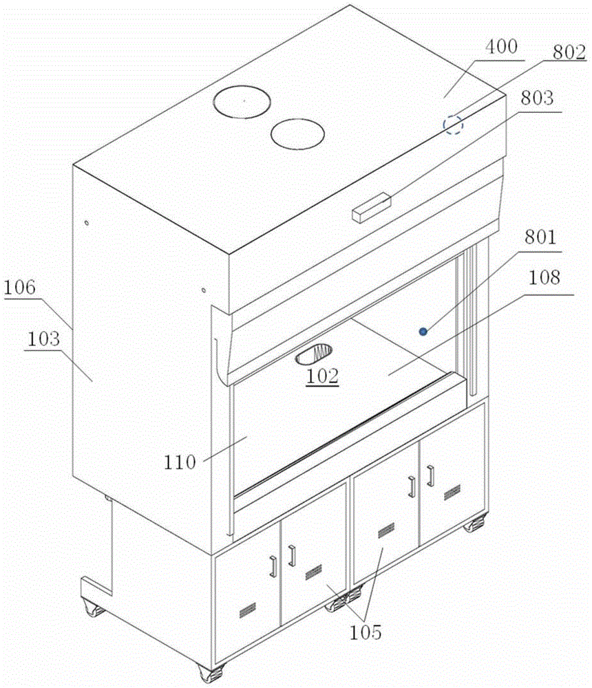
A technology for fume hoods and cabinets, applied in the field of fume hoods, which can solve problems such as the inability to realize exhaust and replenishment air volume, individual adjustment, and poor product quality consistency

Active Publication Date: 2016-11-23
E3 GREEN TECH CO LTD
View PDF17 Cites 21 Cited by
  • Summary
  • Abstract
  • Description
  • Claims
  • Application Information

AI Technical Summary

Problems solved by technology

However, the single make-up air flow of the current new fume hood cannot establish a stable air flow pattern in the working chamber of the fume hood, so the problem of air turbulence and eddy current has not been solved, and the overflow that endangers the health and safety of experimenters risk still exists
In addition, the fume hoods currently on the market all rely on the unified air supply system and exhaust system of the building to obtain power. If multiple fume hoods are used in parallel at the same time, the exhaust and supplementary air volume cannot be adjusted individually according to the usage situation. It also results in higher energy consumption
Moreover, during the installation and commissioning process, the fume hood and its control system are usually temporarily assembled on site using loose parts, so there are problems of high installation cost and poor product quality consistency

Method used


Image

  • Ventilation hood
  • Ventilation hood
  • Ventilation hood

Examples


Embodiment Construction

[0065] Now referring to the drawings, the preferred embodiments of the present invention will be described in detail. Although the description of the present invention will be introduced in conjunction with this preferred embodiment, this does not mean that the features of this invention are limited to this embodiment. On the contrary, the purpose of introducing the invention in combination with the embodiments is to cover other options or modifications that may be extended based on the claims of the invention. In order to provide an in-depth understanding of the present invention, the following description will contain many specific details. The present invention can also be implemented without using these details. In addition, in order to avoid confusion or obscuring the focus of the present invention, some specific details will be omitted in the description.

[0066] In addition, the "up", "down", "left", "right", "top", and "bottom" used in the following description are bas...


PUM


Abstract

The invention provides a ventilation hood which is capable of reducing air-conditioning energy consumption, restraining hazardous substance effusion from a working chamber, and achieving the effects of low installation cost and high consistency of product quality. The ventilation hood comprises a hood body, an air supplement system and an air exhaust system; an inner chamber of the hood body is used as the working chamber, and a front opening opened towards indoor environment is formed in the front wall of the hood body; the air supplement system is connected with an air supplement passage of a building for working chamber air supplement; the air exhaust system is connected with an air exhaust passage of the building, and air entering the working chamber through the front opening and air entering the working chamber through the air supplement system are exhausted from the working chamber; the positions, on the upper portion and the lower portion of the hood body, of the air supplement system are each provided with at least an air supplement opening, and the air supplement openings supply air towards the working chamber; a top module is arranged on the hood body, and an air supplement draught fan and an air supplement valve for the air supplement system and an air exhaust draught fan and an air exhaust valve for the air exhaust system are arranged inside the top module; and air supplement passages which connect the air supplement draught fan and the air supplement valve with the air supplement openings communicate with one another.

Description

Technical field [0001] The invention relates to a fume hood, in particular to a ventilation type fume hood. Background technique [0002] The fume hood can generally be described as a ventilated working space used to capture, contain, and remove exhaust gas, harmful gases and particulate matter. Most of the traditional fume hoods use a large amount of ambient air from the front opening of the fume hood to the working cavity of the fume hood, and at the same time use a high-power fan to exhaust air in the working cavity to contain and treat harmful substances in the air. Under the design concept of the traditional fume hood, the higher the air volume sent from the front opening, the more effective the fume hood is to control and discharge harmful substances in the air. Therefore, the building's HVAC system must be used to transfer the space where the fume hood is used. For example, a large amount of air is added to the laboratory to replace the ambient air sent into the fume hood...

Claims


Application Information

Patent Timeline
Patent Type & Authority Applications(China)
IPC IPC(8): B08B15/02
Inventor 阮红正唐光野
Owner E3 GREEN TECH CO LTD
Learn More