
Liquid crystal grating, control method thereof, 3D display panel and display device

A liquid crystal grating and display panel technology, applied in the field of 3D display, can solve the problems that the liquid crystal grating cannot meet the demand, and the vertical slit grating cannot realize the random switching between horizontal and vertical directions.

Active Publication Date: 2016-11-16
WANWEI CLOUD VISION SHANGHAI DIGITAL TECH CO LTD
View PDF5 Cites 17 Cited by
  • Summary
  • Abstract
  • Description
  • Claims
  • Application Information

AI Technical Summary

Problems solved by technology

[0004] In view of this, the purpose of the embodiment of the present invention is to provide a liquid crystal grating and its control method, a 3D display panel and a display device to solve the problem of vertical The slit grating cannot realize random switching between horizontal and vertical, so the existing liquid crystal grating cannot meet the needs of practical applications

Method used


Image

  • Liquid crystal grating, control method thereof, 3D display panel and display device
  • Liquid crystal grating, control method thereof, 3D display panel and display device
  • Liquid crystal grating, control method thereof, 3D display panel and display device

Examples


Embodiment 1

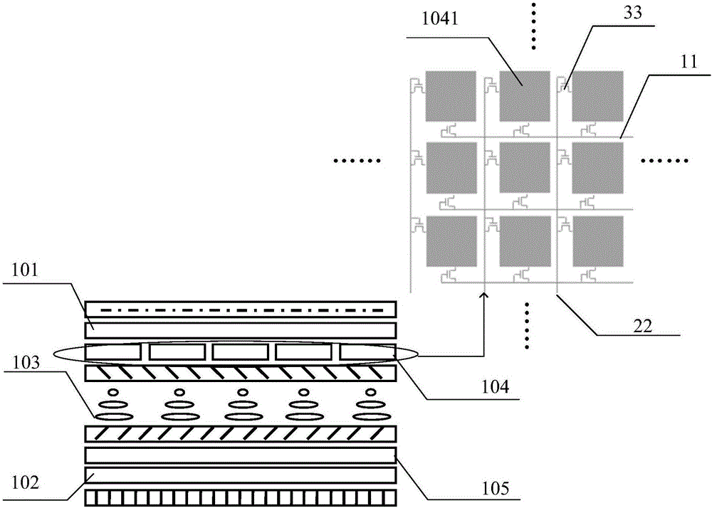
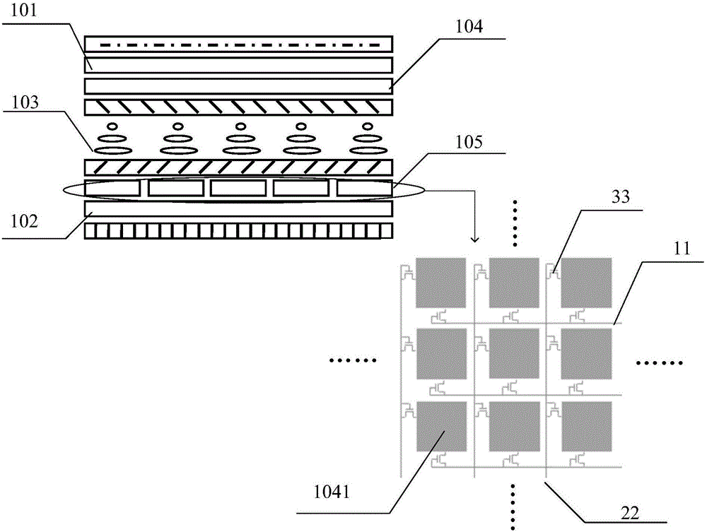
[0040] Such as Figure 1a and as Figure 1b Two schematic diagrams of the structure of the liquid crystal grating shown, the liquid crystal grating includes an upper substrate 101 and a lower substrate 102 oppositely arranged, and a first grating electrode 104 formed on the upper substrate 101, and a first grating electrode 104 formed on the lower substrate 102. Two grating electrodes 105, a liquid crystal layer 103 is arranged between the first grating electrode 104 and the second grating electrode 105;

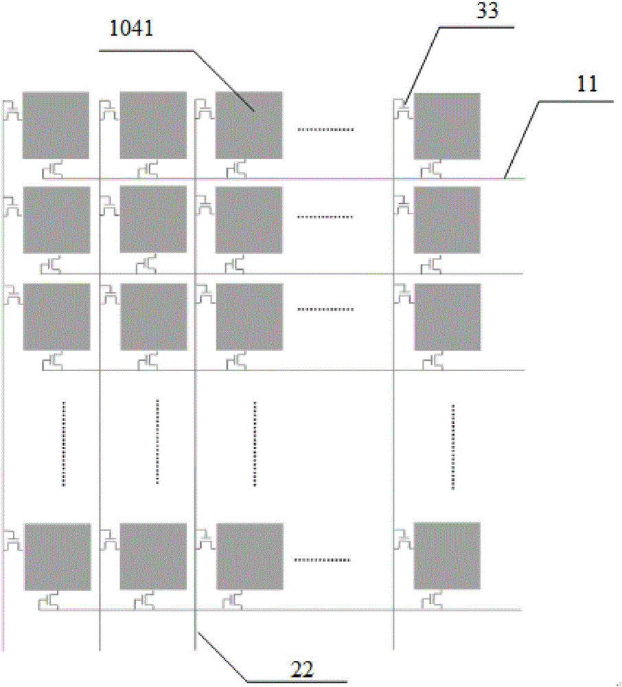
[0041] Considering that the electrode pattern can be made on the first grating electrode 104, and the electrode pattern can also be made on the second grating electrode, any one of the first grating electrode 104 and the second grating electrode 105 has an electrode pattern, and the electrode pattern determines the narrow gap. Corresponding to the shape of the slit grating, the other grating electrode is an overall transparent electrode, which can be grounded to GND, specifi...

Embodiment 2

[0067] The embodiment of the present invention also provides a 3D display panel, such as Figure 8 As shown, the 3D display panel 60 includes a 2D display screen and a liquid crystal grating 601 as described in the first embodiment, and the liquid crystal grating 601 is arranged on the light emitting side of the above-mentioned 2D display screen.

[0068] The specific implementation process of the 3D display panel 60 is similar to that of the liquid crystal grating 601 described above, and reference may be made to the above embodiment of the liquid crystal grating 601 , and repeated descriptions will not be repeated here.

[0069] Wherein, the screen size of the liquid crystal grating 601 is generally consistent with the screen size of the supporting 2D display screen 602, and the liquid crystal grating 601 is arranged on the light-emitting side of the 2D display screen 602, and the 2D display screen and the liquid crystal grating 601 can be bonded to each other through a bondi...

Embodiment 3

[0075] The embodiment of the present invention also provides a 3D display device, such as Figure 9 As shown, the 3D display device 1 includes the 3D display panel 60 as described in the second embodiment.

[0076] Specifically, the above-mentioned 3D display device 1 may be a display, and the above-mentioned 3D display panel 60 is arranged in the casing of the display through a specific circuit connection relationship, wherein, the screen size of the 60 kinds of liquid crystal gratings 601 of the 3D display panel is generally the same as that of the matching used The 2D display screen 602 has the same screen size, and the liquid crystal grating 601 is arranged on the light emitting side of the 2D display screen 602 , and the lower substrate 102 of the liquid crystal grating 601 and the upper substrate 101 of the 2D display screen 602 share the same substrate.

[0077] In the 3D display device 1 provided by the embodiment of the present invention, the display device includes a...


PUM


Abstract

The invention provides a liquid crystal grating and a control method thereof, a 3D display panel and a display device. A first grating electrode in the liquid crystal grating comprises a plurality of grating sub-electrodes arranged in an arrayed mode. A second grating electrode is a whole clear electrode. Or, the second grating electrode comprises a plurality of grating sub-electrodes arranged in an arrayed mode. The first grating electrode is a whole transparent electrode. The multiple grating sub-electrodes on each row are connected with a row driving line through a plurality of control switches. The multiple grating sub-electrodes on each column are connected with a column driving line through the multiple control switches. According to the embodiment, the electrode pattern on the grating electrode is designed into the mode that the multiple grating sub-electrodes are distributed in the arrayed mode, the row driving line or the column driving line is controlled to apply an electric signal alternately, the liquid crystal layer is pervious to light partially and not pervious to light partially, slits are formed at intervals, electric control signals are used for adjusting the shape and direction of gratings formed on the liquid crystal layer, and therefore transverse or longitudinal random switching o the 3D display effect is achieved.

Description

technical field [0001] The invention relates to the technical field of 3D display, in particular to a liquid crystal grating and a control method thereof, a 3D display panel and a display device. Background technique [0002] At present, with the continuous development of liquid crystal display technology, the application of naked-eye 3D technology is also becoming more and more mature. The specific implementation method is to assemble a grating module composed of a switch liquid crystal screen, a polarizing film and a polymer liquid crystal layer on the surface of the display panel. In the three-dimensional display mode, under certain working conditions, the liquid crystal layer and the polarizing film can form vertical stripes with a width of tens of microns, blocking part of the view, so that the left eye of the viewer only receives the left eye view, and the right eye only receives the view. The right-eye view creates a 3D image effect by separating the visual images of...

Claims


Application Information

Patent Timeline
Patent Type & Authority Applications(China)
IPC IPC(8): G02F1/1343G02B27/22
CPCG02F1/134309G02B30/27
Inventor 刘竹徐小丽
Owner WANWEI CLOUD VISION SHANGHAI DIGITAL TECH CO LTD
Learn More