
An installation structure of an evaporator and an overhead air conditioner for a vehicle

An installation structure and evaporator technology, which is applied to vehicle parts, transportation and packaging, air treatment equipment, etc., can solve the problems of low installation efficiency and safety hazards of evaporators, and achieve the effect of strengthening strength

Active Publication Date: 2018-11-16
GREE ELECTRIC APPLIANCES INC
View PDF7 Cites 0 Cited by
  • Summary
  • Abstract
  • Description
  • Claims
  • Application Information

AI Technical Summary

Problems solved by technology

[0005] Therefore, the technical problem to be solved by the present invention is to overcome the defects of low installation efficiency and potential safety hazards in the existing evaporator installation process.

Method used


Image

  • An installation structure of an evaporator and an overhead air conditioner for a vehicle
  • An installation structure of an evaporator and an overhead air conditioner for a vehicle
  • An installation structure of an evaporator and an overhead air conditioner for a vehicle

Examples


Embodiment 1

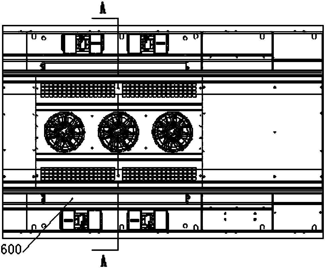
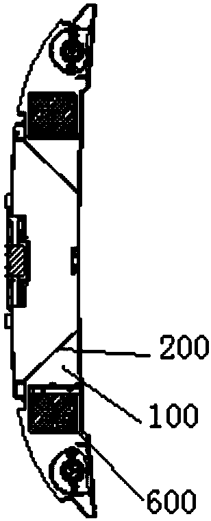
[0045] The mounting structure provided by this embodiment is used for vehicle roof air conditioners, such as Picture 1-1 with 1-2 As shown, the roof-mounted air conditioner for a vehicle includes two evaporators 600 arranged on the roof of the vehicle, and two installation structures corresponding to the two evaporators 600 one by one, Picture 1-1 100 in the center is the return air outlet, Picture 1-1 The A-A direction in the middle is the front and rear sides, and the two sides perpendicular to the A-A direction are the left and right sides. Figure 1-2 The middle support plate 200 is installed on the roof (ie, the flat plate on the right in the figure), and the roof corresponds to the bottom side of the roof-mounted air conditioner for the vehicle.

[0046] Such as Figures 2-1 to 2-3 , Figure 3-1 to Figure 3-3 , Figures 4-1 to 4-4 and Figure 5 As shown, the installation structure provided by this embodiment includes two spaced extension walls 201 arranged on the i...

Embodiment 2

[0056] Such as Figure 6-1 , Figure 6-2 with Figure 6-3 As shown, in the installation structure provided by this embodiment, the fixed limit pin on each extension wall 201 is changed to one, and the through hole on the protruding end of the supporting plate is changed to one correspondingly, and the rest of the structure and installation process are implemented in the same way. example.

Embodiment 3

[0058] The mounting structure provided by this embodiment is the same as that of Embodiment 1 except for the locking part. Such as Figure 7 As shown, the locking component 400 in this embodiment includes a limit block 405, a pressing slider 406 with a guiding slope, and a fastener 404 set through the pressing slider 406, and the pressing slider 406 is away from The surface on one side of the mounting surface is a long bottom surface; during operation, the fastener 404 drives the pressing slider 406 to move toward the mounting surface, and the guide slope of the pressing slider 406 clamps the frame member 300, and lock the bottom of the fastener 404 into the hole structure 202 provided on the mounting surface.


PUM


Abstract

The invention provides a mounting structure of an evaporator and a vehicle to-mounted air-conditioner. The mounting structure comprises two extension walls, a frame part, a guide limiting part and a locking part. The two extension walls are arranged on the mounting face of an air return supporting plate in a spaced mode; the air return supporting plate is mounted on a vehicle roof; an air return opening is formed between the air return supporting plate and the vehicle roof; and the mounting face is located on one side of the air return opening and arranged basically perpendicular to the vehicle roof. The frame part is used for mounting the evaporator, and two protruding ends are arranged on the side face, close to the mounting face, of the frame part in a spaced mode, and the two protruding ends correspond to the two extension walls one by one in position. The guide limiting part comprises a through hole and a limiting protrusion part, and the evaporator is limited by matched connection of the through hole and the limiting protrusion part. The locking part is arranged on the mounting face and used for being in matched connection with a hole structure on the mounting face, so that the rear side face of the frame part in the mounting direction is fixed. The mounting structure overcomes the defects that the mounting efficiency is low and potential safety hazards exist in the mounting process of the evaporator.

Description

technical field [0001] The invention relates to the technical field of vehicle air conditioners, in particular to an installation structure of an evaporator and a vehicle overhead air conditioner. Background technique [0002] Vehicle air conditioners are composed of compressors, condensers, evaporators, fans and necessary control components, which are used to adjust the temperature and humidity in the vehicle and provide the occupants with an air conditioning system that provides a comfortable environment. At present, vehicle air conditioners are mostly installed on the roof, and the installation method is usually to install the compressor, condenser, evaporator and other components on the roof in sequence. [0003] Existing vehicle air conditioners generally include two evaporators, which are arranged one-to-one on both sides in the width direction of the roof, and each evaporator is installed on a corresponding return air support plate. The return air support plate inclu...

Claims


Application Information

Patent Timeline
Patent Type & Authority Patents(China)
IPC IPC(8): B60H1/00
CPCB60H1/00521
Inventor 吴多德刘星茂蔡正永徐如好李建涛吴信会王高峰
Owner GREE ELECTRIC APPLIANCES INC
Learn More