Automatic discharging system of plate pressing machine
A technology of automatic discharging and pressing machine, applied in the direction of presses, manufacturing tools, etc., can solve the problems of consuming manpower and material resources, time and effort, inconvenience, etc., and achieve the effect of small space occupation, high production efficiency and scientific design
- Summary
- Abstract
- Description
- Claims
- Application Information
AI Technical Summary
Problems solved by technology
Method used
Image
Examples
Embodiment 1
[0036] Such as Figure 1-Figure 3 As shown, a platen machine automatic discharge system is installed on the discharge end of the platen machine 21, including a platen machine discharge device 22, a lifting platform 24 set corresponding to the platen machine discharge device 22, and a platform for holding the platen. The three-layer mobile trolley 23 and the controller that respectively control and connect the discharging device 22 and the lifting platform 24 of the pressing machine, wherein the controller is connected to the discharging device 22 of the pressing machine so as to control the discharging of the pressing plate, and the control The device controls and connects the lifting platform 24 to move up and down so as to drive the support plates 25 of each layer of the mobile trolley 23 to dock with the platen discharge device 22 .
[0037] The discharge device 22 of the press plate machine includes a hydraulic stroke rod 1, a guide device cooperating with the hydraulic st...
Embodiment 2
[0042] Such as Figure 4 As shown, the difference between this embodiment and Embodiment 1 is that an arc-shaped plate 12 is arranged on the hydraulic stroke rod 1 corresponding to the turning track of the turnover plate 2, and a first position sensor is installed on the arc-shaped plate 12. The controller is connected to the first position sensor so as to control the first hydraulic push rod 3 to push the turnover plate 2 into place, and the induction probe A8 of the first position sensor and the induction probe B9 of the first position sensor can be respectively set at The horizontal position and the vertical position of the flap realize the automatic control of the flap.
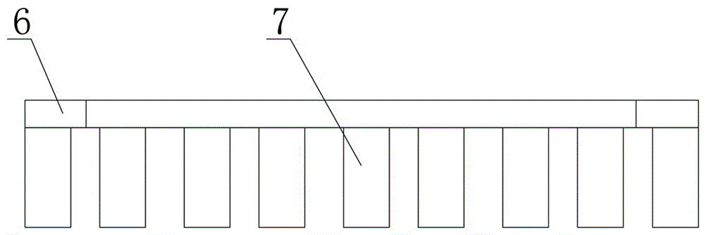
[0043] Such as Figure 5 As shown, a second position sensor is set on the turnover plate 2 corresponding to the slide bar 6 or the baffle plate 7, and the controller is connected to the second position sensor so as to control the second hydraulic push rod 4 to push the The discharge stopper described ab...
PUM
 Abstract
Description
Claims
Application Information
 - R&D
- Intellectual Property
- Life Sciences
- Materials
- Tech Scout
- Unparalleled Data Quality
- Higher Quality Content
- 60% Fewer Hallucinations
Browse by: Latest US Patents, China's latest patents, Technical Efficacy Thesaurus, Application Domain, Technology Topic, Popular Technical Reports.
© 2025 PatSnap. All rights reserved.Legal|Privacy policy|Modern Slavery Act Transparency Statement|Sitemap|About US| Contact US: help@patsnap.com


