Connector, printed board assembly and wafer assembly

A technology for connectors and printed boards, which is applied in the installation, connection, electrical components and other directions of connecting components, can solve problems such as connector damage, and achieve the effect of improving elasticity and improving deformation capacity.

Active Publication Date: 2016-11-09
CHINA AVIATION OPTICAL-ELECTRICAL TECH CO LTD
View PDF6 Cites 2 Cited by
  • Summary
  • Abstract
  • Description
  • Claims
  • Application Information

AI Technical Summary

Problems solved by technology

[0004] The purpose of the present invention is to provide a connector with a large amount of mating floating, which is used to solve the problem that the existing connector is easily damaged when it is inserted into the printed board assem...

Method used


Image

  • Connector, printed board assembly and wafer assembly
  • Connector, printed board assembly and wafer assembly
  • Connector, printed board assembly and wafer assembly

Examples


specific Embodiment 1

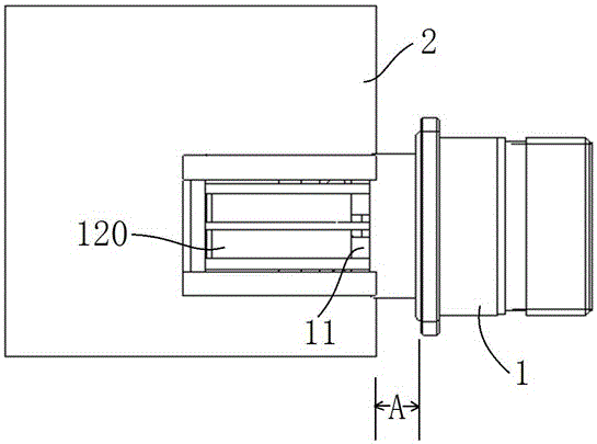
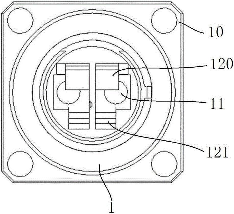
[0020] The first specific embodiment of the connector of the present invention is a transfer connector installed on the panel of the box body and used to realize the conversion of the printed board assembly in the box and the external plug connector. Specifically, a connector housing 1 is included, and a front contact 11 extending forward and backward is arranged inside the connector housing 1 , and the front contact 11 is a pin contact, and is used for plugging and mating with an adapted plug connector.

[0021] The rear end of the front contact piece 11 is also fixedly connected with a rear contact piece, and when the connector is installed on the box body panel through the connecting flange 10 on its shell, the back contact piece extends into the box body. Such as figure 1 As shown, the position A in the figure is the position of the cabinet panel after the actual installation is completed, and the cabinet panel is no longer shown here.

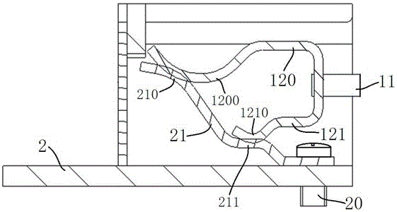
[0022] The rear contact piece has ...


PUM


Abstract

The invention provides a connector, a printed board assembly and a wafer assembly. The connector comprises a connector shell, wherein the connector shell is internally provided with a front contact piece extending forwards and backwards; a rear contact piece is fixedly arranged at the rear end of the front contact piece; and a connecting contact end for mutual pressing and contact with the adapting contact end of an adapting contact piece to realize elastic deformation in a plug connection process is arranged at the rear end of the rear contact piece. Through the arrangement of the connecting contact end in contact with the adapting contact end in a pressing manner to realize elastic deformation, the floating quantity of the contact piece in the plug connection process is increased, and the contact piece in the plug connection process is prevented from being damaged by forced mounting.

Description

technical field [0001] The invention relates to a conductive connection device, in particular to a connector, a printed board assembly and a contact piece assembly. Background technique [0002] When providing power to the printed board in the cabinet, it is often necessary to provide a socket electrically connected to the printed board in the cabinet on the cabinet for plugging in the power plug. The Chinese invention patent with the application publication date of 2015.11.11 and the application number of 201510361202.3 discloses an equipment cabinet. This equipment cabinet includes a cabinet body with a mounting panel, and a printed board is arranged in the cabinet and is electrically connected to the printed board. The auxiliary socket is the printed board assembly, and the auxiliary socket is equipped with an L-shaped bent cylindrical pin, that is, a transfer contact, and a transfer socket that is mated with the auxiliary socket, that is, a connector, is fixed outside th...

Claims


Application Information

Patent Timeline
IPC IPC(8): H01R13/73H01R13/74H01R12/71H01R12/91
CPCH01R12/716H01R12/91H01R13/73H01R13/74
Inventor 张翔刘向阳
Owner CHINA AVIATION OPTICAL-ELECTRICAL TECH CO LTD
Why Eureka
Try Eureka