


Quick Research
Generate reliable direction feasibility study reports for your R&D in just a few steps.

Technical Q&A
Discover and master advanced knowledge NOW. Basics, ideas, possibilities, all at once.

Find Solutions
As an expert in R&D theories, this can generate solutions to your technical problems instantly.

Evaluate Feasibility
Analyze your overall solution with one click, know your potential R&D risks in advance.

Monitor Landscape
Get weekly tech updates, stay abreast of the latest tech innovations and key insights.
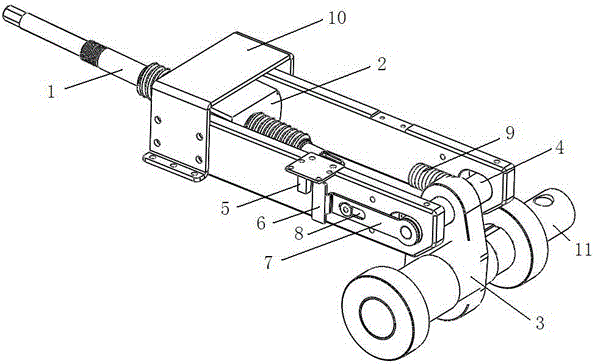
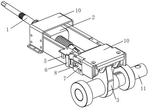
A rotary movement blocking detecting mechanism controlled by a linear pair
A technology of rotary motion and linear pairing, applied in the field of detection mechanism, can solve problems such as lack of transmission, damage to the mechanical structure of power transmission, and difficult maintenance
- Summary
- Abstract
- Description
- Claims
- Application Information
AI Technical Summary
Problems solved by technology
Method used
Image

Examples
Embodiment Construction
[0015] The present invention will be specifically introduced below in conjunction with the accompanying drawings and specific embodiments.
[0016] A detection mechanism for blocked rotation movement controlled by a linear pair, comprising a slot box, a linear auxiliary mechanism composed of a push rod 1 and a wire sleeve 2 is arranged in the cavity at one end of the slot box, and a The through hole accommodates the swing shaft 4 connected with the swing arm 3 in the through hole.
[0017] The thread sleeve 2 is connected with the push rod 1 through threads, and matches with the cavity of the groove box. It fixes the position of the push rod 1 in the cavity of the groove box, and reciprocates with the push rod 1 .
[0018] The length of the through hole is greater than the diameter of the balance shaft 4, which is convenient for the balance shaft 4 to slide in the through hole.
[0019] The outer wall of the tank box is provided with a sliding piece 7 with a chute 8 , one end...
PUM
 Abstract
Description
Claims
Application Information
 - R&D Engineer
- R&D Manager
- IP Professional
- Industry Leading Data Capabilities
- Powerful AI technology
- Patent DNA Extraction
Browse by: Latest US Patents, China's latest patents, Technical Efficacy Thesaurus, Application Domain, Technology Topic, Popular Technical Reports.
© 2024 PatSnap. All rights reserved.Legal|Privacy policy|Modern Slavery Act Transparency Statement|Sitemap|About US| Contact US: help@patsnap.com