
Electromagnetic valve and air gap control method of electromagnetic valve

A solenoid valve and air gap technology, applied in the direction of valve operation/release device, valve lift, valve details, etc., can solve problems such as difficulties, low reliability, and increased production costs of valve stems, and achieve high production efficiency and high performance Stable, highly reliable results

Active Publication Date: 2016-11-09
JASMIN INT AUTO RES ANDDEV BEIJING CO LTD
View PDF4 Cites 9 Cited by
  • Summary
  • Abstract
  • Description
  • Claims
  • Application Information

AI Technical Summary

Problems solved by technology

[0020] The purpose of the present invention is to provide a solenoid valve and an air gap control method for the solenoid valve to solve the problems of existing solenoid valves, such as numerous valve stem groupings and difficulties in production and inventory management, and the additional surface grinding process of the valve stem increases the production cost , low matching and assembling efficiency of the valve stem, and problems of unstable performance and low reliability of the solenoid valve

Method used


Image

  • Electromagnetic valve and air gap control method of electromagnetic valve
  • Electromagnetic valve and air gap control method of electromagnetic valve
  • Electromagnetic valve and air gap control method of electromagnetic valve

Examples


Embodiment Construction

[0048] Embodiments of the present invention will be further described in detail below in conjunction with the accompanying drawings and examples. The following examples are used to illustrate the present invention, but should not be used to limit the scope of the present invention.

[0049] In the description of the present invention, it should be noted that the terms "center", "longitudinal", "transverse", "upper", "lower", "front", "rear", "left", "right", " The orientations or positional relationships indicated by "vertical", "horizontal", "top", "bottom", "inner" and "outer" are based on the orientations or positional relationships shown in the drawings, and are only for the convenience of describing the present invention and Simplified descriptions, rather than indicating or implying that the device or element referred to must have a particular orientation, be constructed and operate in a particular orientation, and thus should not be construed as limiting the invention. ...


PUM


Abstract

The invention relates to the technical field of electromagnetic control, and provides an electromagnetic valve and an air gap control method of the electromagnetic valve. The electromagnetic valve comprises a valve seat and a valve core, wherein the valve core moves relative to the valve seat under the actions of a magnetic control unit and a reset unit, and closes or opens the electromagnetic valve; the valve core comprises an armature and a valve stem; the armature is provided with an assembly hole; and a first end of the valve stem is inserted into the assembly hole and forms an interference fit with the assembly hole. According to the electromagnetic valve, the valve core can adapt to the valve seats with different sizes only by adjusting the length of the valve stem in the valve core positioned outside the armature without arranging a plurality of valve stems or grinding the end surface of the valve stem; and the valve stem with proper length can be selected without the aid of any standard measuring stick. Therefore, the electromagnetic valve has the advantages of high production efficiency and low cost. Besides, since the first end of the valve stem is inserted into the armature, the problem of the abrasion of the contact part between the end surface of the armature and the end surface of the valve stem does not exist; and therefore, the electromagnetic valve has the advantages of stable performance and high reliability.

Description

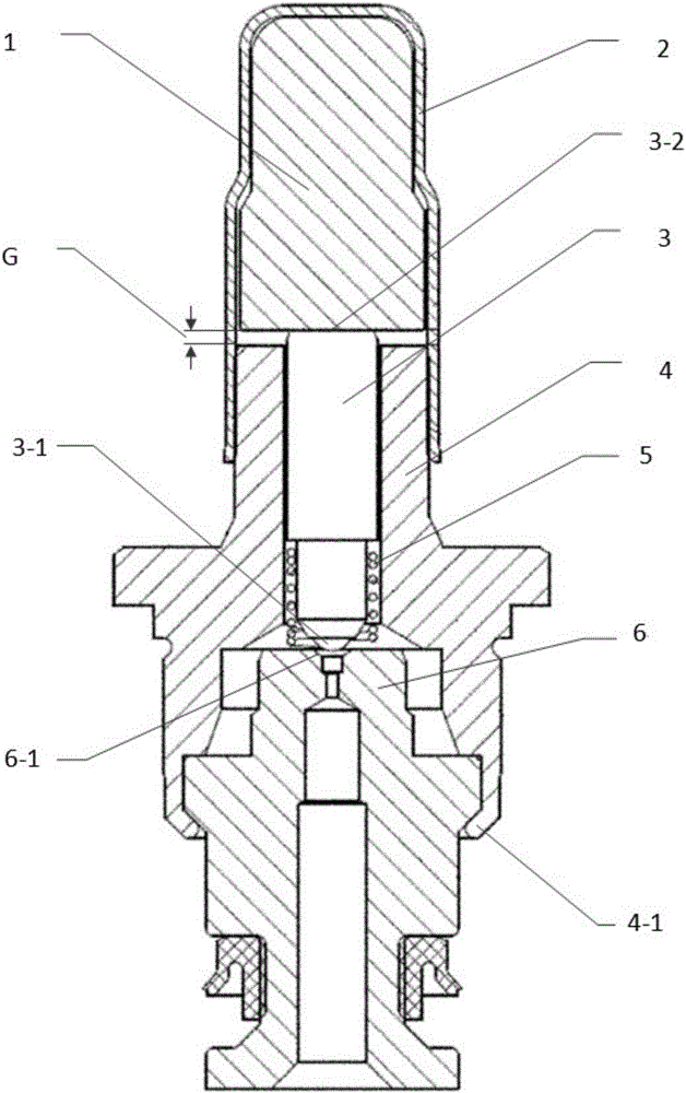
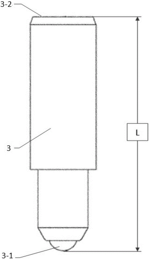
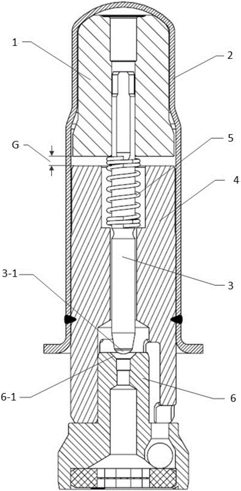
technical field [0001] The invention relates to the technical field of electromagnetic control, in particular to a solenoid valve and an air gap control method for the solenoid valve, and more specifically to a normally open solenoid valve suitable for automobile anti-lock braking systems or vehicle body electronic stability control systems , and the air gap control method of the solenoid valve. Background technique [0002] A conventional structure for traditional solenoid valves such as figure 1 As shown, it includes an armature 1, a valve sleeve 2, a valve stem 3, a valve housing 4, a return spring 5 and a fixed seat 6. The armature 1 and the valve stem 3 form the valve core, the valve housing 4 and the fixed seat 6 form the valve seat, and the valve core can move relative to the valve seat, so that when the valve core moves to different positions of the valve seat, the solenoid valve can be closed or opened. valve. [0003] Specifically, the valve stem 3 includes a fi...

Claims


Application Information

Patent Timeline
Patent Type & Authority Applications(China)
IPC IPC(8): F16K1/36F16K31/06
CPCF16K1/36F16K31/0655
Inventor 陈言平万磊向世水覃赞文
Owner JASMIN INT AUTO RES ANDDEV BEIJING CO LTD
Learn More