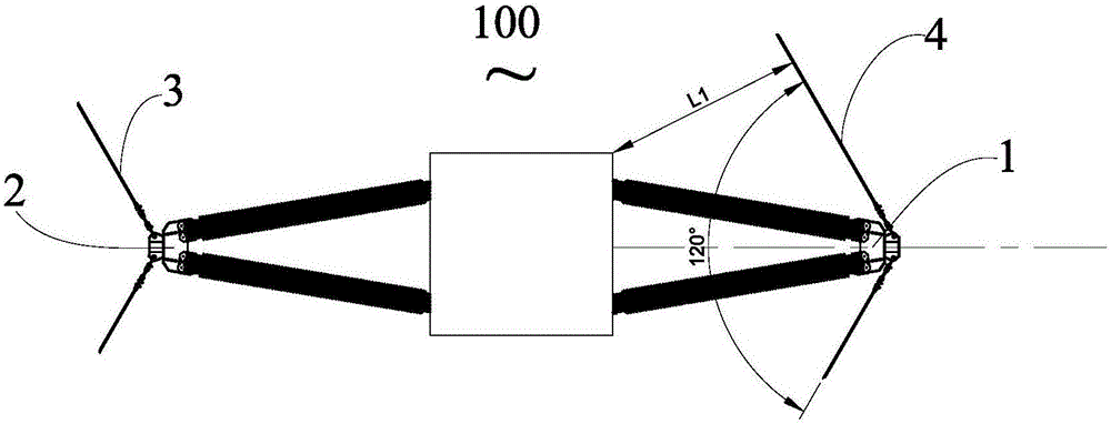
Cross arm and angle tower
A technology of corner towers and cross-arms, which is applied to towers, building types, buildings, etc., and can solve problems such as cross-arms increasing production difficulty
- Summary
- Abstract
- Description
- Claims
- Application Information
AI Technical Summary
Problems solved by technology
Method used
Image
Examples
Embodiment 1
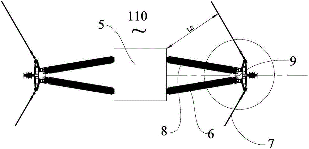
[0025] figure 2 Shown is a schematic diagram of the use of the corner tower 110 at the corner of the line. The corner tower 110 includes a tower body 5 and a cross arm 6 arranged on the tower body 5 , and the wires 7 at the corner are respectively hung on the cross arm 6 . In this embodiment, the turning angle of the wire 7 is 120°.
[0026] In this embodiment, the cross arm 6 is a V-shaped composite cross arm, the V-shaped open end is connected to the tower body 5 , and the apex is a free end for connecting the wire 7 . The cross-arm 6 includes two cross-arm insulators 8 and free ends, and the two cross-arm insulators 8 are fixed by end fittings 9 at the free ends.
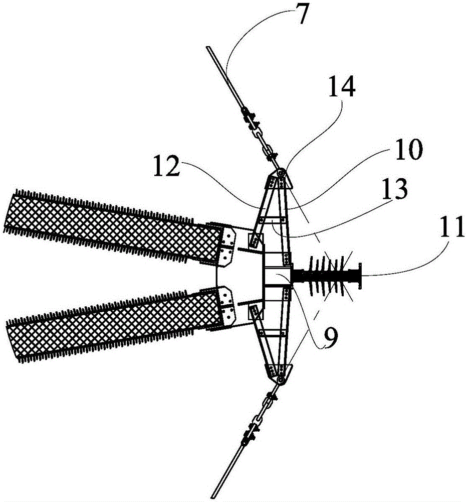
[0027] The partial enlarged picture of the free end of the cross arm is as follows: image 3 As shown, the free end of the cross arm includes an end fitting 9 , an extension piece 10 and a jumper device 11 . Specifically, extension pieces 10 are respectively provided on both sides of the end fitting 9 , one e...
Embodiment 2
[0036] Such as Figure 4 and Figure 5 As shown, in this embodiment, the extension piece 15 is fixed on the end fitting 16 as a whole, and the corner wires 17 are respectively connected to both ends of the extension piece 15 . Different from the first embodiment, the extension piece 15 of this embodiment is formed by connecting five brackets 18 with different lengths. The corresponding number of brackets can be selected according to the needs and assembled into an extension of the required length to meet the electrical clearance between the wire and the tower body. In addition, when the extension piece needs to be longer, it is more flexible to use multi-segment bracket assembly. In this implementation, a reinforcing piece and an auxiliary piece are also provided at the free end of the cross arm, and their function and structure are the same as those in Embodiment 1, and will not be repeated here.
Embodiment 3
[0038] The extension piece of the present invention does not limit its applied cross-arm structure, material, and wire transfer angle. Such as Figure 6 As shown, in the present embodiment, the cross arm 19 on the corner tower 120 is a straight cross arm, the wire 20 turns over at an angle of 100°, and the angle between the corner wire 20 and the center line of the cross arm 19 is 50°. In this embodiment, extension pieces are provided at both inner and outer corners.
[0039]Specifically, the cross arm 19 includes a cross arm insulator 21 and a free end away from the tower body 22 , and the free end includes an end fitting 23 and an extension piece 24 connected to the end fitting 23 . The extension piece 24 is a rectangular plate, its inclination angle in the vertical plane is 60°, and the two included angles with the center line of the cross arm 19 are respectively 70° and 110°. Since any angle between the extension piece 24 and the center line of the cross arm 19 is greate...
PUM
 Abstract
Description
Claims
Application Information
 - Generate Ideas
- Intellectual Property
- Life Sciences
- Materials
- Tech Scout
- Unparalleled Data Quality
- Higher Quality Content
- 60% Fewer Hallucinations
Browse by: Latest US Patents, China's latest patents, Technical Efficacy Thesaurus, Application Domain, Technology Topic, Popular Technical Reports.
© 2025 PatSnap. All rights reserved.Legal|Privacy policy|Modern Slavery Act Transparency Statement|Sitemap|About US| Contact US: help@patsnap.com


