
Improved decorative film cutting machine

A film cutting machine and decorative film technology, applied in the directions of transportation and packaging, metal processing, winding strips, etc., can solve the problems of hot cutting knives, low efficiency, time-consuming and laborious, etc. Prevent high temperature, good cooling effect

Active Publication Date: 2016-11-09
ZHEJIANG SHANGCHENG SCI&TECH
View PDF6 Cites 22 Cited by
  • Summary
  • Abstract
  • Description
  • Claims
  • Application Information

AI Technical Summary

Problems solved by technology

The decorative film shipped from the factory is generally wound on a roller and sent to various dealers in batches. Each dealer needs to cut the rolled decorative film according to the different uses of the purchased decorative film by different buyers. For example, use For the furniture seller who attaches the decorative film to the furniture, a large number of cut decorative films with a certain length and width are required, which requires a large amount of cutting of the rolled decorative film. The traditional cutting method is Use a ruler to draw lines on the decorative film, and then use cutting tools, such as utility knives and scissors, to cut, which is time-consuming and laborious, and the efficiency is not high enough
For mass cutting, currently on the market, machines are used for cutting, the decorative film is conveyed through the conveying mechanism, and then the decorative film is cut by the cutting knife of the cutting mechanism. It is inconvenient to adjust the length of the decorative film cutting. In the process of repeatedly cutting the decorative film, a large amount of heat will be generated, which will cause the cutter to become hot. When cutting, it is easy to burn the cutting edge of the decorative film and affect the quality of the decorative film.

Method used


Image

  • Improved decorative film cutting machine
  • Improved decorative film cutting machine
  • Improved decorative film cutting machine

Examples


Embodiment Construction

[0029] The following are specific embodiments of the present invention and in conjunction with the accompanying drawings, the technical solutions of the present invention are further described, but the present invention is not limited to these embodiments.

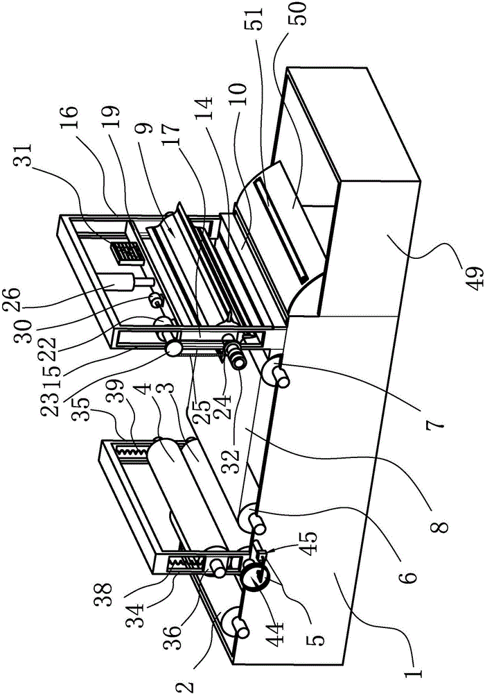
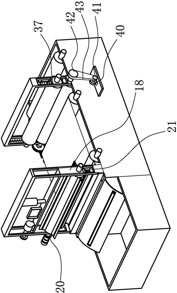
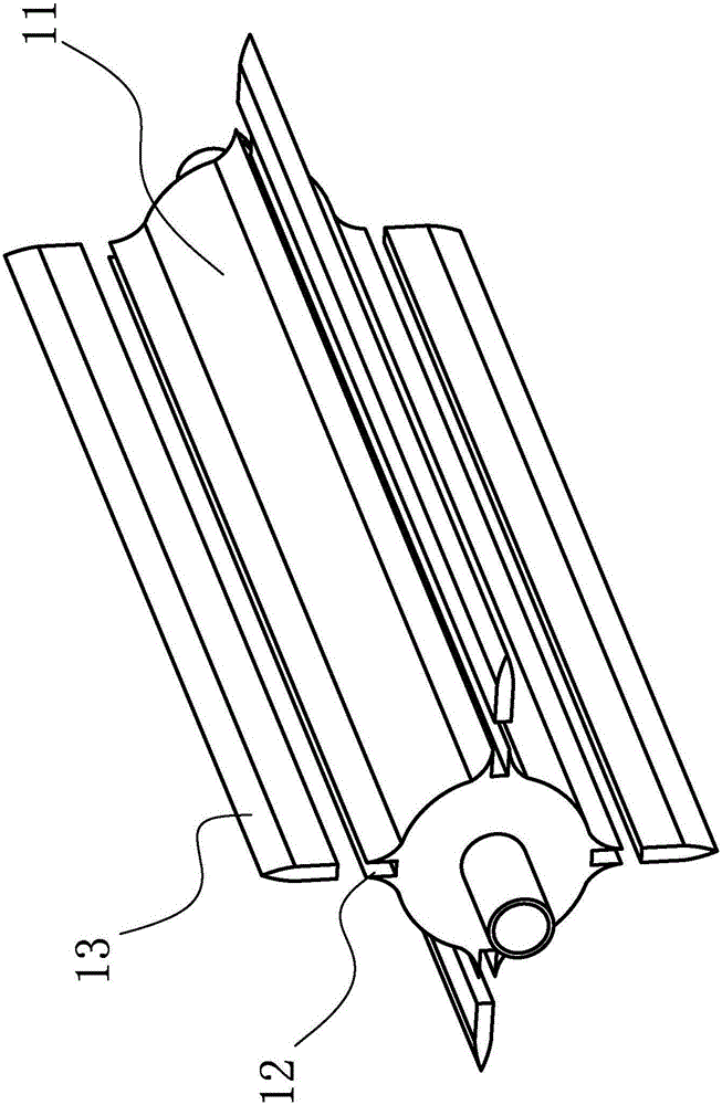
[0030] like figure 1 , figure 2 , image 3 , Figure 4 and Figure 5 As shown, an improved decorative film cutting machine includes a chassis 1, the chassis 1 has an inner cavity, the top of the chassis 1 has an opening communicating with the inner cavity, and one end of the top of the chassis 1 is provided with a roll for the decorative film 2 to be rotated and placed. The placement slot is characterized in that the improved decorative film cutting machine includes a conveying mechanism, a conveying mechanism, a cutting mechanism and a storage mechanism for collecting the cut decorative film;

[0031] The conveying mechanism comprises a conveying roller one 3 and a conveying roller two 4, the conveying roller one 3 r...


PUM


Abstract

The invention provides an improved decorative film cutting machine and belongs to the technical field of machines. By the adoption of the improved decorative film cutting machine, the problem that an existing decorative film cutting machine generates heat in the working process, and accordingly a cut product is poor in quality is solved. The improved decorative film cutting machine comprises a machine case. The machine case is provided with an inner cavity. An opening communicating with the inner cavity is formed in the top of the machine case. A containing groove used for rotatably containing a coiled decorative film is formed in one end of the top of the machine case. The improved decorative film cutting machine is characterized by comprising a conveying mechanism, a transferring mechanism, a cutting mechanism and a storage mechanism, wherein the storage mechanism is used for collecting the cut decorative film. The improved decorative film cutting machine has the advantages that a cutter can be effectively cooled, and the decorative film is prevented from being burnt.

Description

technical field [0001] The invention belongs to the technical field of decorative film cutting and relates to an improved decorative film cutting machine. Background technique [0002] Decorative film is widely used in daily life and has a wide range of functions, such as: anti-UV, blocking direct ultraviolet rays for skin health; Glass, office glass, etc. can be used; free cutting, full of DIY fun. The decorative film shipped from the factory is generally wound on a roller and sent to various dealers in batches. Each dealer needs to cut the rolled decorative film according to the different uses of the purchased decorative film by different buyers. For example, use For the furniture seller who attaches the decorative film to the furniture, a large number of cut decorative films with a certain length and width are required, which requires a large amount of cutting of the rolled decorative film. The traditional cutting method is Use a ruler to draw lines on the decorative fi...

Claims


Application Information

Patent Timeline
IPC IPC(8): B26D1/36B26D7/26B26D7/08B26D7/28B65H20/02B65H29/20
CPCB26D1/365B26D5/20B26D7/08B26D7/2614B26D7/2642B26D7/28B26D2007/322B26F1/38B26F1/44B26F2001/3886B65H20/02B65H29/20B65H2404/1521
Inventor 张伟忠苏跃锋施叶标汪琴伟
Owner ZHEJIANG SHANGCHENG SCI&TECH
Learn More