
Rapid blank centering device of cold rolling mill

A technology of cold rolling mill and centering device, applied in the direction of guide/positioning/alignment device, etc., can solve the problems of damaged feeding chain, too high or insufficient height, broken guide device, etc., to simplify operation and protect The effect of the device

Active Publication Date: 2016-11-09
ZHEJIANG MINGHE STEEL PIPE CO LTD
View PDF6 Cites 0 Cited by
  • Summary
  • Abstract
  • Description
  • Claims
  • Application Information

AI Technical Summary

Problems solved by technology

The wall of the steel pipe will hit the core rod, causing damage to the feeding chain; the core rod cannot be inserted into the blank tube and the guide device will be damaged
The second jacking up will also appear too high or not enough, directly hitting the front claw

Method used


Image

  • Rapid blank centering device of cold rolling mill
  • Rapid blank centering device of cold rolling mill

Examples


Embodiment Construction

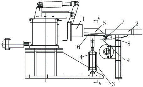
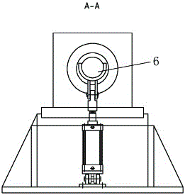
[0011] Combine below figure 1 with figure 2 Specific description embodiment:

[0012] A rapid centering device for cold-rolled pipe mill blanks. The rapid centering device for cold-rolled pipe mill blanks includes a gripping mechanism 1 and a feeding device 2. The middle of the feeding device 2 and the gripping mechanism 1 A guide mechanism 3 is provided, and the guide mechanism 3 includes a cylinder 4 and a guide groove 5. The end of the guide groove 5 close to the catch mechanism 1 is a U-shaped guide groove 6, and the front end of the U-shaped guide groove 6 is inserted into the claw mechanism 1 One end of the guide groove 5 close to the feed device 2 is arranged on the top of the feed device through the rotating shaft mechanism 7, the guide groove is a chute, and the end of the guide groove close to the feed device gradually rises toward the end close to the grabbing mechanism ; The blank enters the guide groove from the feeding device, and comes out from the U-shaped g...


PUM


Abstract

The invention belongs to the technical field of appliances of cold rolling mills, and particularly relates to a rapid blank centering device of a cold rolling mill. The rapid blank centering device of the cold rolling mill comprises a clamping and grasping mechanism and a feeding device; a guiding and connecting mechanism is arranged between the feeding device and the clamping and grasping mechanism; and a blank passes through a slope in a guide groove and comes out of a U-shaped guide groove to be in butt joint with a core rod. The rapid blank centering device of the cold rolling mill has the beneficial effects that operation is simplified, secondary operation of adjusting the height of a feeding chute and the centering device is avoided when specifications of blanks are replaced, and a feeding chain and a front clamping jaw are protected from being damaged by impact of pipe blanks.

Description

technical field [0001] The invention belongs to the technical field of cold-rolled pipe mill equipment, and in particular relates to a rapid centering device for cold-rolled pipe mill stock. Background technique [0002] The currently used guide device is a device with a bracket installed on a fixed cylinder at the front jaw of the cold rolling mill. Ideally, the device is jacked up when the material is fed, and the height of the centerline of the mandrel is firstly jacked up. When the height of the billet tube center line is the same as that of the billet pipe, the cylinder will fall back after the billet pipe is inserted into the core rod; when the billet pipe is pushed to the front claw, the cylinder will lift up so that it can push the center of the billet pipe to the front of the rolling mill The center of the jaws is high. In the actual production operation process, because the specifications of the billet tube are often changed, it takes a long time and effort to adj...

Claims


Application Information

Patent Timeline
IPC IPC(8): B21B39/14
CPCB21B39/14
Inventor 陶志坚王茂龙林学亮
Owner ZHEJIANG MINGHE STEEL PIPE CO LTD
Learn More